Power management device and method

A power management device and power supply technology, which is applied in the direction of instruments, computer control, simulators, etc., can solve the problems of equipment cost increase, energy consumption increase, ATX power supply can not realize the timing start function, etc., to achieve equipment cost reduction, ultra-low power consumption effect

Inactive Publication Date: 2015-01-21
SHANGHAI DATANG MOBILE COMM EQUIP +1
View PDF4 Cites 7 Cited by
  • Summary
  • Abstract
  • Description
  • Claims
  • Application Information

AI Technical Summary

Problems solved by technology

This leads to a very large standby power consumption of the ATX power management module (about 100mA). Currently, the ATX power management module does not support external power supply, so a portable device such as automatic drive test needs to be equipped with a large-capacity lithium battery to power the power management module in the device. Control power supply for CPU of automatic drive test equipment in standby state
[0005] In addition, it can be seen from the above that the existing ATX power supply cannot realize the function of timing start-up, and the power consumption is relatively large during standby, and a lithium battery with a large capacity needs to be used, resulting in an increase in equipment cost and energy consumption.

Method used


Image

  • Power management device and method
  • Power management device and method
  • Power management device and method

Examples


Embodiment Construction

[0033] The power management device and method provided by the present invention will be described in more detail below with reference to the drawings and embodiments.

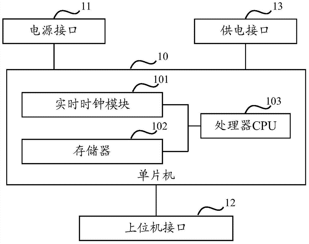
[0034] An embodiment of the present invention provides a power management device, such as figure 1 shown, including:

[0035] A power interface 11 connected to a power supply;

[0036] The host computer interface 12 connected with the host computer;

[0037] A power supply interface 13 connected to each communication board of the automatic drive test equipment;

[0038] The single-chip microcomputer 10 connected with the power supply interface 11 includes a real-time clock module 101, a memory 102 and a processor CPU103;

[0039] Wherein, the processor CPU 103 downloads the timing switch information of the automatic drive test equipment from the host computer through the host computer interface 12 and stores it in the memory 102. The real-time clock module 101 determines when the power-on time is reached acc...


PUM


Abstract

The invention relates to a power management device and method. The device comprises a power interface connected with a power source, an upper computer interface connected with an upper computer, a power supply interface connected with communication single plates of an automatic circuit test device and a single-chip microcomputer connected with the power supply interface; the single-chip microcomputer comprises a real-time clock module, a storage device and a CPU, wherein the CPU downloads timing starting and stopping information of the automatic circuit test device from the upper computer through the upper computer interface and stores the timing starting and stopping information in the storage device, the CPU is waken up when the real-time clock module determines that the starting time is up according to the real-time clock and the stored timing starting and stopping information, the CPU is triggered to be stopped when it is determined that the stopping time is up, and the CPU supplies power to the communication single plates of the automatic circuit test device through the power supply interface after work is done. By means of the power management device and method, the function of conducting multi-time-period timing starting / stopping to supply power to the automatic circuit test device can be achieved; meanwhile, when the device is in the standby state, ultra-low power dissipation is achieved, and the device cost is reduced.

Description

technical field [0001] The invention relates to the technical field of power management, in particular to a power management device and method. Background technique [0002] Automatic drive test equipment needs to control the operation of multiple communication modules and record relevant test data, so it generally uses X86 architecture industrial control boards. The general X86 architecture industrial control board is equipped with ATX (AT eXternal) power control module, and the ATX power management module controls the power-on. Specifically, after manually triggering the PWR_BTN# signal to start the boot, each part of the ATX power management module is started step by step. Provides power to automated drive test equipment. [0003] The ATX power supply cannot realize the automatic timing power-on function, and can only be powered on by manually triggering the PWR_BTN# signal. [0004] Through the system software architecture, it is possible to realize the scheduled shutd...

Claims


Application Information

Patent Timeline
Patent Type & Authority Applications(China)
IPC IPC(8): G05B19/042
CPCG05B19/4188
Inventor 刘征
Owner SHANGHAI DATANG MOBILE COMM EQUIP
Why Eureka
Try Eureka