Signal input circuit for disaster prediction terminal
A signal input circuit, terminal technology, applied in computer control, general control systems, instruments, etc., can solve the problems of strong interference of low-voltage signals, influence of precision and accuracy, etc., to improve accuracy, easy to implement, and circuit structure. simple effect
- Summary
- Abstract
- Description
- Claims
- Application Information
AI Technical Summary
Problems solved by technology
Method used
Image
Examples
Embodiment 1
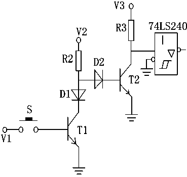
[0022] Such as figure 1 A signal input circuit for a disaster prediction terminal is shown, including a triode T1 and a triode T2, the base of the triode T1 is connected to the power supply V1 through a switch S, and the collector of the triode T1 is connected to a diode On the cathode of D1, the anode of the diode D1 is connected to the power supply V2 through the resistor R2, the anode of the diode D1 is connected to the base of the transistor T2, and the collector of the transistor T2 is connected to the input of the chip 74LS240 The terminal is connected to the power supply V3 through the resistor R3, the voltage values of the power supply V1, the power supply V2 and the power supply V3 decrease in turn, and the emitters of the triode T1 and the triode T2 are grounded.
Embodiment 2
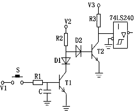
[0024] Such as figure 2 A signal input circuit for a disaster prediction terminal shown in this embodiment is roughly the same as that of Embodiment 1, and is only optimized on the basis of Embodiment 1, that is, the base of the triode T1 is connected with filter circuit.
[0025] The filter circuit includes a resistor R1 and a capacitor C. Both ends of the resistor R1 are respectively connected to the base of the transistor T1 and the switch. One end of the capacitor is grounded and the other end is connected to the resistor R1.
[0026] A diode D2 is connected between the base of the transistor T2 and the anode of the diode D1, and the anode of the diode D2 is connected to the anode of the diode D1.
Embodiment 3
[0028] Such as figure 1 and figure 2 A signal input circuit for a disaster prediction terminal shown in this embodiment is refined on the basis of the above embodiments, that is, the voltage value of the power supply V1 is 24V, and the voltage value of the voltage V2 is The value is 5V. The power supply V3 can adopt any value less than 5V, but it should be greater than the voltage value of the microprocessor.
[0029] First, refine the signal input circuit of the present invention with respect to a specific embodiment. In a specific embodiment, the resistors R1, R2 and R3 can be 100 ohms, 200 ohms and 200 ohms respectively, and the capacitor C can be 100 μF. Diode D1 and diode D2 can use IN4001, triode T1 and triode T2 can use 2SDV2A0.75W.
PUM
 Abstract
Description
Claims
Application Information
 - R&D
- Intellectual Property
- Life Sciences
- Materials
- Tech Scout
- Unparalleled Data Quality
- Higher Quality Content
- 60% Fewer Hallucinations
Browse by: Latest US Patents, China's latest patents, Technical Efficacy Thesaurus, Application Domain, Technology Topic, Popular Technical Reports.
© 2025 PatSnap. All rights reserved.Legal|Privacy policy|Modern Slavery Act Transparency Statement|Sitemap|About US| Contact US: help@patsnap.com


