Shifting register and driving method thereof as well as grid electrode driving circuit and display device

A shift register and capacitor technology, applied in static memory, digital memory information, instruments, etc., can solve problems such as uneven horizontal bright lines and bright lines on the screen, inability to guarantee turn-off voltage, affecting display quality, etc. Interference, ensure display quality, and eliminate the effect of parasitic coupling effects

Active Publication Date: 2015-01-21
BOE TECH GRP CO LTD +1
View PDF5 Cites 28 Cited by
  • Summary
  • Abstract
  • Description
  • Claims
  • Application Information

AI Technical Summary

Problems solved by technology

[0004] When a certain row of pixels is in the non-selection period, the shift register corresponding to this row needs to be able to output the voltage (hereinafter referred to as the shutdown voltage) that makes each driving thin film transistor (driving TFT) of this row of pixels turn off, but the existing The shift register mostly uses the clock signal, and the non-selection period is longer. If the clock signal changes during the non-selection period, the shift register is affected by the parasitic capacitance effect of its internal circuit, and it cannot guarantee the operation of the non-selection period. It can provide a stable off voltage at every moment, which will easily lead to unstable output. When it is applied to the gate drive of LCD panels, it will cause uneven horizontal bright lines and bright lines on the screen, which will affect the display quality.

Method used


Image

  • Shifting register and driving method thereof as well as grid electrode driving circuit and display device
  • Shifting register and driving method thereof as well as grid electrode driving circuit and display device
  • Shifting register and driving method thereof as well as grid electrode driving circuit and display device

Examples


Embodiment 1

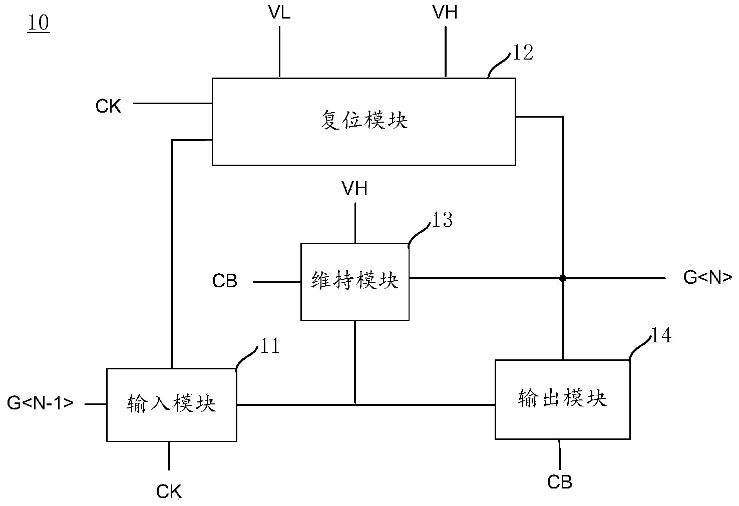
[0045] An embodiment of the present invention provides a shift register 10, such as figure 1 As shown, the shift register 10 includes: an input module 11, which sends input to the output module 14, the reset module 12 and the maintenance module 13 according to the signal G input from the signal input terminal and the signal CK input from the first clock signal terminal. Signal; the reset module 12 is connected to the input module 11 and the signal output terminal, and resets the signal output terminal according to the signal CK input by the first clock signal terminal, the first level signal VL, the second level signal VH and the input signal; The maintenance module 13 is connected to the input module 11 and the output module 14, and sends to the output module 14 to eliminate the parasitic coupling effect according to the signal sent by the input module 11, the signal CB input by the second clock signal terminal, and the second level signal VH Affected maintenance signal; outp...

Embodiment 2

[0083] The embodiment of the present invention also provides a gate drive circuit, such as Figure 7 As shown, the gate drive circuit includes a plurality of cascaded shift registers 10 described in Embodiment 1, wherein the signal output terminals of each stage of shift register 10 are connected to a gate scanning line (Fig. not shown in ), and, except that the signal input end of the first stage shift register 10 inputs the start pulse signal, the signal input end of any stage shift register 10 is connected to the signal of the upper stage shift register 10 The output terminal, the signal output terminal of any stage shift register 10 is all connected to the signal input terminal of the next stage shift register 10;

[0084] The first clock signal terminal and the second clock signal terminal of any stage shift register 10 respectively input two mutually inverse clock signals (such as the first clock signal CK and the second clock signal CB). The first clock signal end...


PUM


Abstract

The invention discloses a shifting register and a driving method thereof as well as a grid electrode driving circuit and a display device, relating to the field of display. A needed electrical level can be stably output and bad phenomena caused by the fact that the output is not stable when a clock signal is converted and an output signal is interfered are eliminated, so that the display quality is guaranteed. According to the shifting register, an input module is used for sending an input signal to an output module, a resetting module and a maintaining module according to an input signal and a first clock signal; the resetting module is connected with the input module and a signal output end and is used for resetting a signal output end according to the first clock signal, first and second electrical level signals and the input signal; the maintaining module is connected with the input module and the output module and is used for sending a maintaining signal to the output module according to the input signal, the second clock signal and the second electrical level signal; and the output module is connected with the input module, the maintaining module and the signal output end and is used for sending the output signal to the signal output end according to the input signal, the maintaining signal and the second clock signal.

Description

technical field [0001] The invention relates to the display field, in particular to a shift register, a driving method thereof, a gate driving circuit and a display device. Background technique [0002] In recent years, Liquid Crystal Display (LCD for short) has developed rapidly due to the advantages of zero radiation, low power consumption, small heat dissipation, small size, accurate image restoration, and sharp character display, and has become the mainstream in the display field. [0003] The pixel array of the liquid crystal display includes several rows of grid scanning lines and several columns of data lines. Among them, the gate drive circuit composed of several shift registers provides signals to several rows of gate scanning lines of the pixel array, so as to control the multiple rows of gate scanning lines to be opened sequentially, and the data lines of the corresponding rows are sent to the pixel array. The pixel electrodes are charged to form the gray-scale v...

Claims


Application Information

Patent Timeline
Patent Type & Authority Applications(China)
IPC IPC(8): G11C19/28G09G3/36
CPCG09G3/3677G09G2310/0286G11C19/28
Inventor 张毅玄明花金泰逵
Owner BOE TECH GRP CO LTD
Why Eureka
Try Eureka