A current detection circuit and an electric current loop control circuit comprising the current detection circuit

A current detection circuit and current detection technology, applied in the direction of measuring current/voltage, control/regulation system, high-efficiency power electronic conversion, etc., can solve the problem of DC-DC output current reduction, reduce circuit power consumption and improve accuracy , the effect of avoiding the overcompensation problem

Active Publication Date: 2015-01-21
SHANGHAI HUALI MICROELECTRONICS CORP
View PDF3 Cites 15 Cited by
  • Summary
  • Abstract
  • Description
  • Claims
  • Application Information

AI Technical Summary

Problems solved by technology

The disadvantage of this method is that although the stability of the loop is guaranteed in the worst case, there is a problem of overcompensation in other cases, which leads to a reduction in the DC-DC output current, and makes the entire structure tend to be a voltage mode DC -DC, lost the advantages of current mode DC-DC itself

Method used


Image

  • A current detection circuit and an electric current loop control circuit comprising the current detection circuit
  • A current detection circuit and an electric current loop control circuit comprising the current detection circuit
  • A current detection circuit and an electric current loop control circuit comprising the current detection circuit

Examples


Embodiment Construction

[0047] The specific embodiment of the present invention will be further described below in conjunction with accompanying drawing:

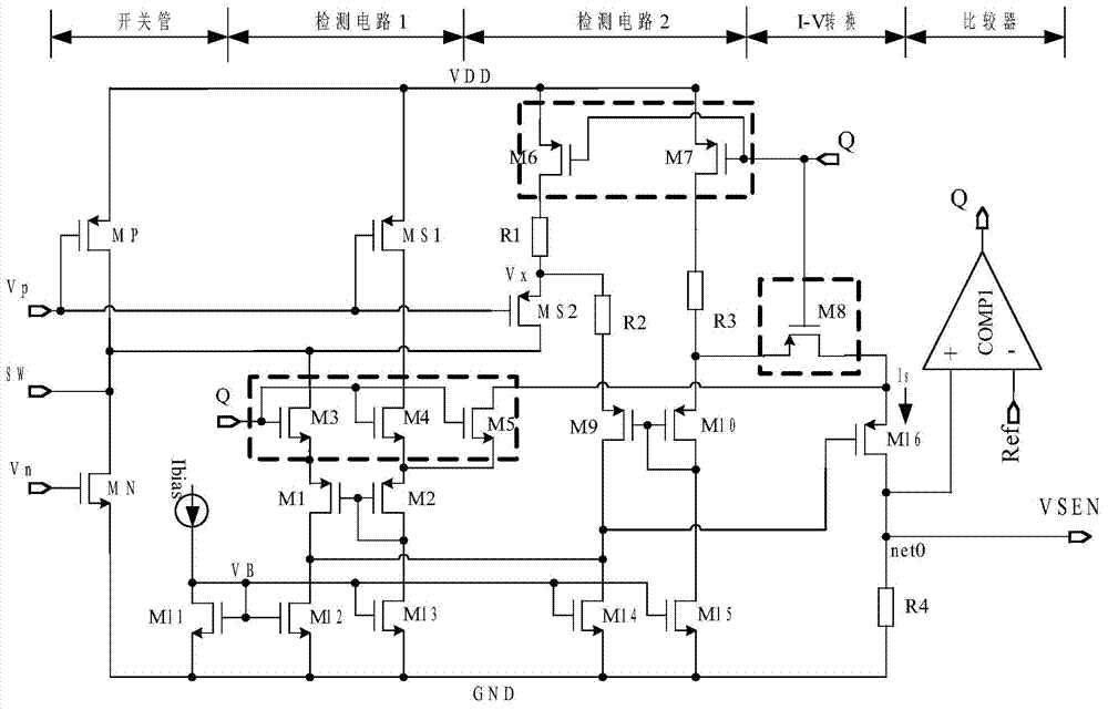
[0048] figure 2 It is a schematic circuit structure diagram of an embodiment of a current detection circuit of the present invention; as figure 2 As shown, a current detection circuit includes a power supply VDD, the power supply VDD is respectively connected with the switch tube (NMOS tube) MP, the first current detection tube (NMOS tube) MS1, the sixth transistor (NMOS tube) M6 and the seventh transistor (NMOS tube) The source terminal (source) of M7 is connected, the switch control terminal Vp is respectively connected with the control terminal (gate) of the switch tube MP, the first current detection tube MS1 and the second current detection tube MS2, and the current output terminal SW They are respectively connected to the drain end (drain) of the switch tube MP, the rectifier tube (PMOS tube) MN, the second current detection tube MS2 and th...


PUM


Abstract

The invention relates to the field of CMOS integrated circuit design and especially relates to a current detection circuit and an electric current loop control circuit comprising the current detection circuit. Through arranging a parallelly-connected MOS transistor current detection circuit and a series resistor current detection circuit, circuit power consumption is reduced at the same time current detection precision is improved; and by utilizing a self-adaption slope compensation circuit, the problem of overcompensation can be further prevented; and detection signals and compensation signals of the circuit can be added directly, thereby facilitating the design of a current-mode DC-DC circuit.

Description

technical field [0001] The invention relates to the field of CMOS integrated circuit design, in particular to a current detection circuit and a current loop control circuit including the current detection circuit. Background technique [0002] Since the current mode DC-DC (direct current) converter (converter) adds a current loop control circuit to the voltage mode DC-DC converter, it can achieve stability compensation more easily, and then compared to the voltage mode DC - DC converters are more widely used. [0003] Among them, the main function of the current loop control circuit in the current mode DC-DC converter is to detect the magnitude of the output current, and quickly feed back the detection results (such as the detected current value, etc.) to the pulse width in the DC-DC circuit. Comparator, and quickly adjust the output of the DC-DC circuit according to the output of the comparator to form a detection-comparison-adjustment current loop, thereby ensuring the st...

Claims


Application Information

Patent Timeline
Patent Type & Authority Applications(China)
IPC IPC(8): H02M3/335G01R19/00
CPCH02M3/156H02M1/0009H02M1/0029H02M1/0048H02M3/1566Y02B70/10
Inventor 王志利张宁蔡俊
Owner SHANGHAI HUALI MICROELECTRONICS CORP
Why Eureka
Try Eureka