Wireless energy and data combined transmission method

A technology of joint transmission and wireless energy, applied in the field of wireless communication, can solve the problems of large transmission rate, short transmission time, unconsidered, etc., and achieve the effect of large transmission rate

Inactive Publication Date: 2015-01-21
NANJING UNIV
View PDF1 Cites 8 Cited by
  • Summary
  • Abstract
  • Description
  • Claims
  • Application Information

AI Technical Summary

Problems solved by technology

The current research work does not consider how to allocate the energy transmission time between the source node and the relay node, the information transmission time, and the information transmission between the relay node and the destination node in the double-hop network with multiple relay nodes. Time, to obtain the shortest transmission time (or maximum transmission rate), has become an urgent problem to be solved

Method used


Image

  • Wireless energy and data combined transmission method
  • Wireless energy and data combined transmission method
  • Wireless energy and data combined transmission method

Examples


example 1

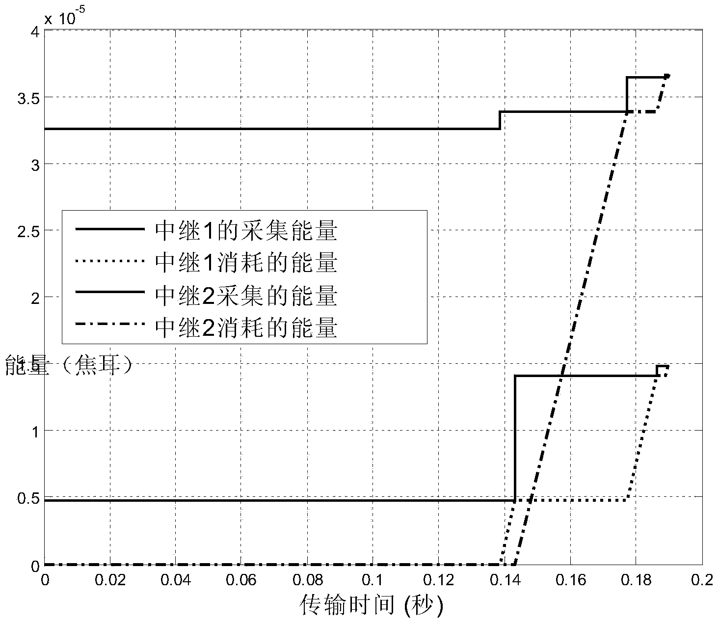
[0033] Such as figure 1 As shown, consider a two-hop network composed of 1 source node, 2 relay nodes and 1 destination node (the relay node is equipped with a radio frequency signal energy acquisition circuit and a signal decoding circuit). For a given set of channel gains, we can calculate the optimal time allocation τ 0 =0.09s,τ 1 =0.02s,τ 2 =0.03s. In the entire sending process, the source node first broadcasts energy to relay 1 and relay 2 in 0.09s; in the time period of 0.09-0.11, the source node sends data to relay node 1, and relay node 2 opportunistically Energy is collected from the signal; within the time period of 0.11-0.14, the source node sends data to the relay node 2, and the relay node 1 opportunistically collects energy from the radio frequency signal. In the relay transmission stage, the transmission sequence is (relay 1, relay 2). It can be seen from the figure that the relays 1 and 2 each go through two transmissions before forwarding all the data to the d...

example 2

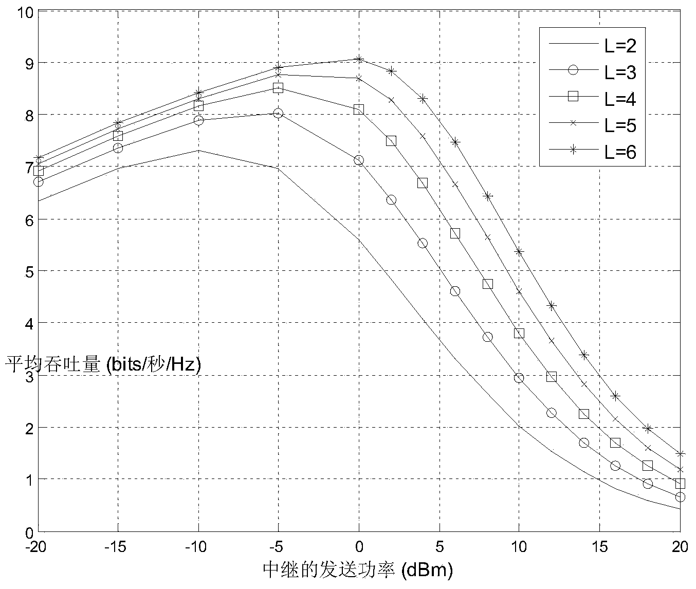
[0035] In this experiment, the signal bandwidth is 10MHz, the power spectral density of the receiver noise is -170dBm / Hz, and the conversion efficiency of the energy harvesting circuit is 0.7. The distance between the source node and the destination node is 6m. Source node transmit power P s = 100mW.

[0036] Such as figure 2 Shown: the relationship between the transmission power of the relay node and the average throughput. In the proposed transmission scheme, the total transmission time includes the energy receiving time of the relay node, the data receiving data of the relay node, and the data sending time of the relay node. The greater the transmitting power of the relay node, the shorter the data transmission time of the node, but the correspondingly longer energy collection time is required. From the figure, we can find the transmission power of the relay node that minimizes the total transmission time.


PUM


Abstract

The invention discloses a wireless energy and data combined transmission method. The method includes the steps that a source node broadcasts the sending sequence of relay nodes through a signaling channel first; the source node broadcasts energy to all the relay nodes in time tau 0; the source node sends data to the l relay node in time tau l, wherein l =1, ..., L; when one of the relay nodes receives the data, other relay nodes can collect energy from a received radio-frequency signal by chance; in the relay sending stage, the relay nodes forward the data received from the source node to a destination node according to the sending sequence, when one relay node sends data, other relay nodes are placed in an energy collecting state, in each sending process, all the energy of the relay nodes is used up, and after sending is completed, the relay nodes broadcast 'END' through the signaling channel, which means that sending is completed. Compared with the prior art, according to the technical scheme, stable energy supply cannot happen to the relay nodes, energy can only be obtained from the radio-frequency signal of the source node, the maximum transmission rate can be achieved, and therefore application value and promotional value are achieved.

Description

Technical field [0001] The invention relates to a wireless communication technology, in particular to a joint transmission method of wireless energy and data. Background technique [0002] In wireless sensor networks, the working time of sensor nodes is often limited by battery power. Using energy harvesting technology to enable sensor nodes to obtain energy from the surrounding environment can effectively extend the working life of the network. With the development of wireless energy transmission technology, in addition to conventional renewable energy sources such as solar energy and wind energy, radio frequency signals have also become a new available energy source[1]. In a communication system using wireless energy transmission technology, information and energy can be transmitted at the same time. How to make the wireless network obtain the best compromise between energy transmission efficiency and information transmission rate is a hot research topic at present. The curr...

Claims


Application Information

Patent Timeline
Patent Type & Authority Applications(China)
IPC IPC(8): H04W28/18
CPCH04W72/0446H04W52/346H04W84/18
Inventor 唐岚张兴敢沈欣
Owner NANJING UNIV
Why Eureka
Try Eureka