Mixing barrel with water flushing scraper blade for chemical use

A mixing tank and scraper technology, which is applied to mixers with rotating stirring devices, mixers, chemical instruments and methods, etc., can solve the problems of high energy consumption of mixers, large stirring resistance, and high heating of the inner wall of the mixing tank. Achieve the effect of improving scraping efficiency and reducing scraping resistance

Inactive Publication Date: 2015-01-28
南通洋口资产经营管理有限公司
View PDF7 Cites 8 Cited by
  • Summary
  • Abstract
  • Description
  • Claims
  • Application Information

AI Technical Summary

Problems solved by technology

[0002] The traditional chemical mixing tank lacks a scraping device. After a period of use, thick chemical raw materials will accumulate on the inner wall of the mixing tank, which will affect the mixing effect and efficiency.
At present, there are chemical mixing tanks with scrapers. The scrapers are connected to the stirring shaft. When the stirring shaft rotates, the scrapers rotate to scrape off the chemical raw materials on the inner wall of the mixing tank. The advantage is to avoid the accumulation of raw materials. However, the disadvantages of the scraper with this structure are: the scraper is always in contact with the inner wall of the mixing tank, and its friction force is relatively large during stirring, which leads to higher heating of the inner wall of the mixing tank and lower stirring resistance. Large, so the energy consumption of the mixer is too high

Method used


Image

  • Mixing barrel with water flushing scraper blade for chemical use

Examples


Embodiment Construction

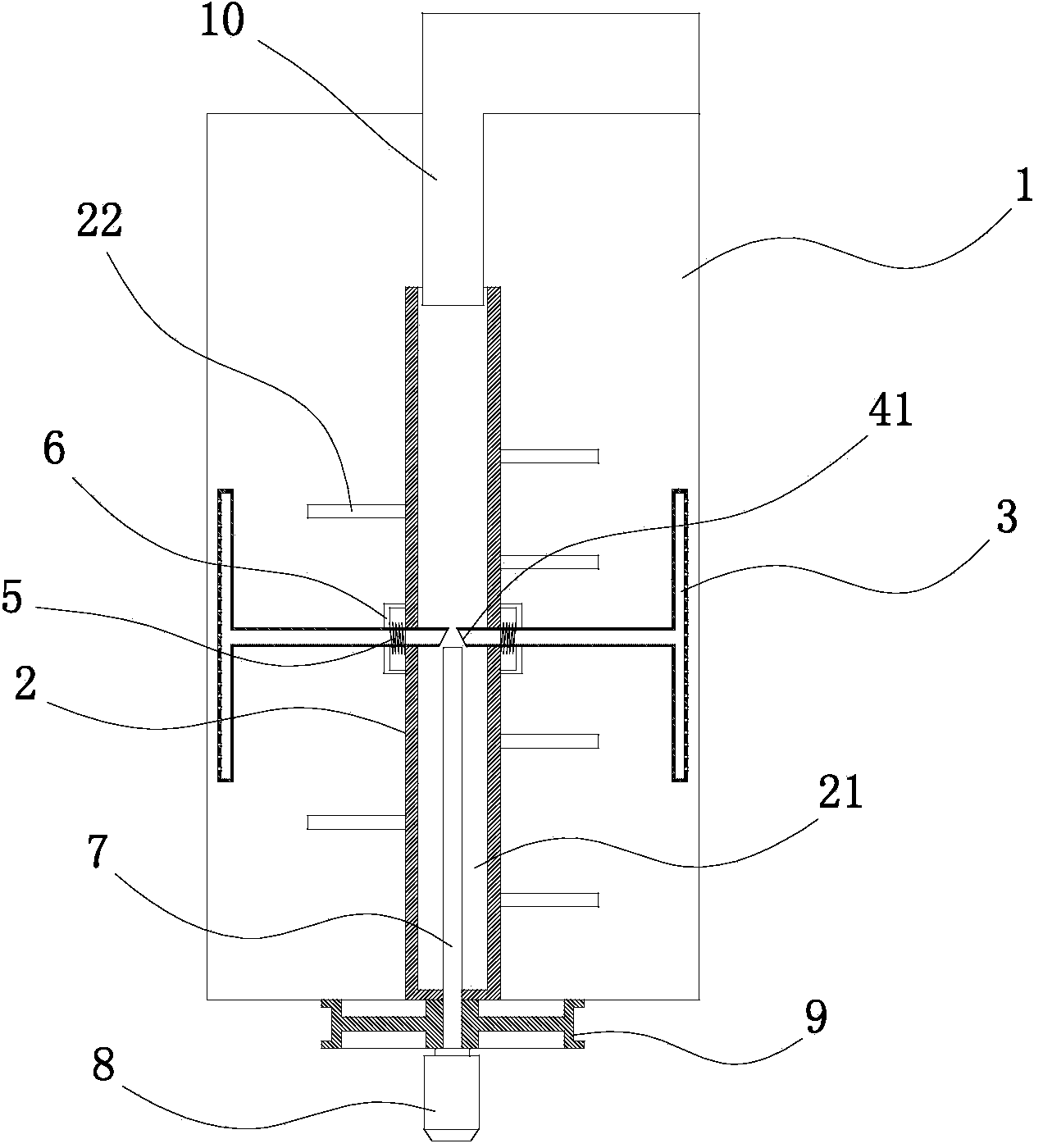
[0015] The specific implementation manner of the present invention will be described below in conjunction with the accompanying drawings.

[0016] Such as figure 1 As shown, the chemical mixing tank with a water flushing scraper in this embodiment includes a mixing tank 1, an agitating shaft 2 installed in the mixing tank 1, and a scraper is installed on the agitating shaft 2 through a connecting rod 4 3. The stirring shaft 2 is a tubular structure with a central through hole 21. The upper end of the stirring shaft 2 has an opening, and its lower end is fixedly connected with a pulley 9, which is connected to the motor through a timing belt; The end surface is fixedly connected with a water inlet pipe 10, and the water outlet end of the water inlet pipe 10 extends into the central through hole 21 of the stirring shaft 2, and its water inlet end is connected with an external water source; The rod is axially fixedly connected with a push rod 7, and the push rod 7 runs through t...


PUM


Abstract

The invention relates to a mixing barrel with a water flushing scraper blade for chemical use. The mixing barrel comprises a mixing barrel, and a stirring shaft arranged inside the mixing barrel, wherein the mixing shaft is of a barrel-shaped structure with a central through hole, the upper end of the stirring shaft is provided with an opening, the lower end of the stirring shaft is fixedly connected with a belt pulley, the upper end surface of the mixing barrel is fixedly connected with a water inlet pipe, the water inlet pipe extends into the central through hole of the stirring shaft and is connected with an external water supply, a cylinder is arranged on the lower surface of the belt pulley, a piston rod of the cylinder is fixedly connected with a mandril, the mandril penetrates through the belt pulley and the mixing barrel to extend into the mixing shaft, two sides of the mixing shaft are provided with scraper blades by virtue of connecting rods, gaps are reserved between the scraper blades and the inner wall of the mixing barrel, the connecting rods and the scraper blades are of shell structures with inner cavities, the side walls of the scraper blades are provided with a plurality of through holes, the connecting rods are connected with the stirring shaft in a manner of sliding in the axial direction, the end parts of the connecting rods are provided with inclined openings and extend into the central through hole of the stirring shaft, the inclined openings are respectively positioned above the mandril, the outer side of the stirring shaft is fixedly connected with mounting sleeves, and the mounting sleeves are internally provided with springs fixedly connected with the outer walls of the connecting rods.

Description

technical field [0001] The invention relates to the technical field of chemical engineering, in particular to a chemical mixing tank. Background technique [0002] The traditional chemical mixing tank lacks a scraping device. After a period of use, thicker chemical raw materials will accumulate on the inner wall of the mixing tank, which will affect the mixing effect and efficiency. At present, there are chemical mixing tanks with scrapers. The scrapers are connected to the stirring shaft. When the stirring shaft rotates, the scrapers rotate to scrape off the chemical raw materials on the inner wall of the mixing tank. The advantage is to avoid the accumulation of raw materials. However, the disadvantages of the scraper with this structure are: the scraper is always in contact with the inner wall of the mixing tank, and its friction force is relatively large during stirring, which leads to higher heating of the inner wall of the mixing tank and lower stirring resistance. La...

Claims


Application Information

Patent Timeline
Patent Type & Authority Applications(China)
IPC IPC(8): B01F7/16B01F15/00
Inventor 宋小林
Owner 南通洋口资产经营管理有限公司
Why Eureka
Try Eureka