Method for preparing heat-insulation pipe by films
A manufacturing method and pipeline technology, applied in the direction of heat insulation protection pipelines, pipeline protection, heat exchange equipment, etc., can solve the problems of heat insulation material damage, etc., and achieve the effect of improving adsorption force and uniform thickness
- Summary
- Abstract
- Description
- Claims
- Application Information
AI Technical Summary
Problems solved by technology
Method used
Image
Examples
Embodiment 1
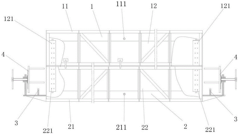
[0041]The mold used in this embodiment is as figure 1 Shown:
[0042] Described mold is split mold and comprises upper mold 1 and lower mold 2, and described upper mold 1 and described lower mold 2 form split mold, and described upper mold 1 and lower mold 2 have shell 11,21 and Corresponding to the shells 11, 21, there are inner tanks 12, 22 with semi-cylindrical cavities installed inside; several through holes 121, 221 are formed on the inner walls of the inner tanks 12, 22, and the inner tanks 12, 22 The outer wall of 22 is provided with cavities 122, 222 communicating with the through holes 121, 221, and at least one of the housings 11, 21 is formed to communicate with the through holes 121, 221 through the cavities 122, 222. The air suction ports 111, 211 are connected to the external vacuum assembly of the mould.
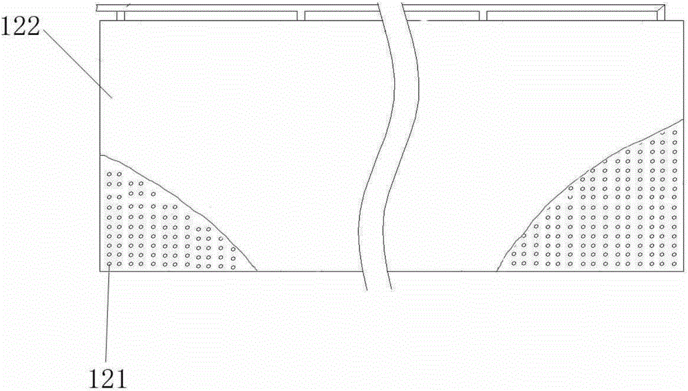
[0043] The through holes 121, 221 are arranged in various ways on the inner tank 12, 22. In this embodiment, the through holes 121, 221 are evenly distribut...
Embodiment 2
[0052] The mold used in this embodiment is a deformation based on the mold in Example 1. The through-hole forming parts are equidistantly arranged along the circumferential direction, and the through-holes 121, 221 are evenly distributed on each of the through-hole forming parts along the axial direction. The liner 12, 22 is provided with several through-hole forming parts equidistantly arranged along the circumferential direction (along the circumferential direction of the mold liner). The holes 121, 221 are axially evenly distributed on each of the through-hole forming parts, such as image 3 As shown, thereby can ensure the pumping effect of the vacuum pumping assembly, make the bag-shaped film 6 and the inner wall of the liner 12,22 adsorb together, and can reduce the chamber 122,222 that communicates with the through hole 121,221 at the same time. The setting area reduces the manufacturing cost of the molding die for the heat insulating layer of the heat insulating pipel...
Embodiment 3
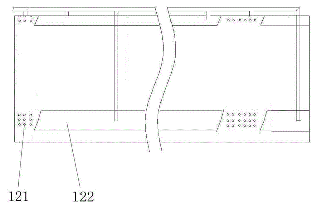
[0055] The mold used in this embodiment is a deformation based on the mold in Example 1. The through-holes 121 , 221 are evenly distributed on the through-hole forming portion along the circumferential direction of the annular through-hole forming portion. The liner 12, 22 is provided with several through-hole forming parts equidistantly arranged along the axial direction (along the length direction of the mold liner), and the through-holes 121, 221 are gathered in the through-hole forming part, and distributed uniformly on each of the via formations, as Figure 4 As shown, thereby can ensure the pumping effect of the vacuum pumping assembly, make the bag-shaped film 6 and the inner wall of the liner 12,22 adsorb together, and can reduce the chamber 122,222 that communicates with the through hole 121,221 at the same time. The setting area reduces the manufacturing cost of the molding die for the heat insulating layer of the heat insulating pipeline and the overall weight of t...
PUM
| Property | Measurement | Unit |
|---|---|---|
| thickness | aaaaa | aaaaa |
Abstract
Description
Claims
Application Information
 - R&D
- Intellectual Property
- Life Sciences
- Materials
- Tech Scout
- Unparalleled Data Quality
- Higher Quality Content
- 60% Fewer Hallucinations
Browse by: Latest US Patents, China's latest patents, Technical Efficacy Thesaurus, Application Domain, Technology Topic, Popular Technical Reports.
© 2025 PatSnap. All rights reserved.Legal|Privacy policy|Modern Slavery Act Transparency Statement|Sitemap|About US| Contact US: help@patsnap.com


