Fully automatic high pressure gas injection control system

A high-pressure gas and control system technology, applied in the field of automatic high-pressure gas injection control system, can solve the problems of unadjustable output gas pressure and flow rate of gas-assisted injection equipment, low production efficiency, and non-presettable gas injection time, etc., to achieve Efficient and reliable effect of control process

Active Publication Date: 2017-02-08
MAXIMATOR SHANGHAI FLUID ENG
View PDF6 Cites 0 Cited by
  • Summary
  • Abstract
  • Description
  • Claims
  • Application Information

AI Technical Summary

Problems solved by technology

[0003] However, most of the gas-assisted injection equipment in the market is manually operated, the production efficiency is low, the gas injection time cannot be pre-set, the gas injection pressure is low, and the injection pressure of ultra-high pressure 70Mpa generally cannot be reached or relies on imports, and the gas-assisted injection equipment outputs gas The pressure and flow cannot be adjusted according to the actual injection molding demand, resulting in waste of production energy
At the same time, because the physical properties of carbon dioxide are solid under ultra-high pressure and normal temperature environments, the temperature of carbon dioxide under high pressure must be changed to make it in a supercritical state. The inert gas medium of high-pressure gas-assisted injection equipment that appears on the market is mostly nitrogen, which cannot Simultaneous realization of CO2 assisted injection molding

Method used


Image

  • Fully automatic high pressure gas injection control system
  • Fully automatic high pressure gas injection control system

Examples


Embodiment Construction

[0014] Below in conjunction with accompanying drawing, content of the present invention is described further:

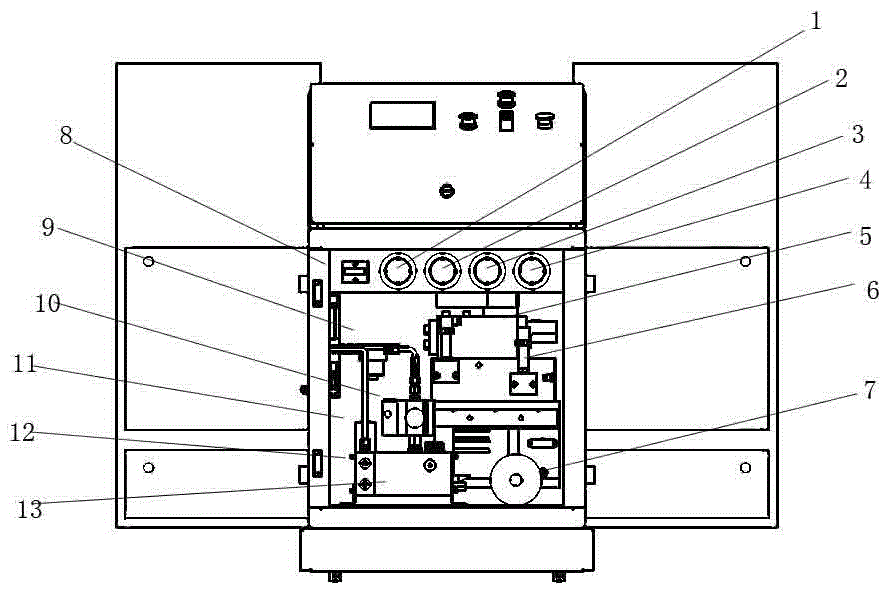
[0015] The automatic high-pressure gas injection control system is mainly composed of the following 10 main parts:

[0016] 1. Gas booster; 2. A set of air intake control device, including intake stop valve, intake stop valve, intake filter, gas cylinder pressure gauge and gas cylinder pressure transmitter; 3. High pressure gas buffer device One set, including gas storage tank, safety valve of gas storage tank, unloading valve of gas storage tank and pressure gauge of gas storage cylinder; 4. One set of air drive device, including driving air filter, driving air pressure gauge, driving air Pressure regulating valve, driving air safety valve, two-position three-way driving air solenoid valve and two-position three-way driving air solenoid valve; 5. Liquid drive pressure flow proportional valve and liquid drive pressure flow proportional valve block; 6. Liquid drive de...


PUM


Abstract

The invention discloses a full-automatic high-pressure gas injection control system in the field of gas-assisted injection equipment. The system comprises a gas booster, a high-pressure gas buffer device, a gas drive device, a liquid drive pressure proportional flow valve, a liquid drive device, a gas drive liquid pump, a pressure signal transmission device and a heating device, wherein an electrical PLC (programmable logic controller) and a touch screen are integrated in a machine cabinet; the gas drive device is used for providing a drive gas source for the gas booster; an external low-pressure gas injection medium is connected to the gas inlet of the equipment; a heating device is arranged at the outlet of the gas booster; pressure transmitters are arranged at the inlet and outlet of the liquid drive pressure proportional flow valve respectively; the pressure transmitters and the proportional flow valve form a feedback closed-loop control system; the same set of gas drive device is shared by the proportional flow valve and the gas booster; the required output maximal pressure grade is set through a pressure adjusting valve of the gas drive device according to the pressure grade of the gas booster. The system has the advantages of high automated degree, diversity of products capable of being subjected to injection moulding, safety, reliability and the like.

Description

technical field [0001] The invention relates to a fully automatic high-pressure gas injection control system in the field of gas-assisted injection molding equipment. Background technique [0002] The automatic high-pressure gas injection control system is a device for gas-assisted injection molding. It is a new type of injection molding process equipment imported from abroad in recent years. It uses high-pressure inert gas to form a vacuum section in the molten plastic to push the molten material forward, realizing injection In the process of pressure holding and cooling, the efficient pressure transmission of gas is used to keep the pressure inside the airway consistent, eliminate internal stress, and prevent product deformation. Gas-assisted injection molding can also reduce product weight, eliminate sink marks, and improve production efficiency. advantage. In household appliances, automobiles, cables, furniture and other industries, gas-assisted injection molding has be...

Claims


Application Information

Patent Timeline
Patent Type & Authority Patents(China)
IPC IPC(8): B29C45/57B29C45/77
CPCB29C45/57B29C45/77B29C2945/76498
Inventor 何天峰曹洁梁兴龙
Owner MAXIMATOR SHANGHAI FLUID ENG
Why Eureka
Try Eureka