Automatic multi-direction material carrying, loading and unloading equipment

A loading and unloading equipment, multi-directional technology, applied in the direction of transportation and packaging, lifting devices, hoisting devices, etc., can solve the problems of consuming manpower and material resources, unsuitable handling methods, low intelligence level, etc., to achieve large working space and save Manpower and time, the effect of high control accuracy

Active Publication Date: 2015-01-28
UNIV OF ELECTRONIC SCI & TECH OF CHINA
6 Cites 34 Cited by

AI-Extracted Technical Summary

Problems solved by technology

These transportation methods generally have the disadvantages of low level of intelligence, fixed operating routes and placement locations, only suitable for handling items of a single size, low guidance accuracy, high manufacturing costs, and labor and material resourc...

Abstract

The invention discloses automatic multi-direction material carrying, loading and unloading equipment which comprises a vertical lifting platform, an X/Y direction horizontal feeding device and a loading/unloading working table, wherein the vertical lifting platform is used for carrying a material in the vertical direction; the X/Y direction horizontal feeding device is used for carrying the material on a plane in the X/Y direction; the loading/unloading working table is used for placing, loading and unloading the material; the X/Y direction horizontal feeding device is mounted on the vertical lifting platform; the loading/unloading working table is mounted on the X/Y direction horizontal feeding device; the loading/unloading working table is provided with a loading/unloading manipulator. The automatic multi-direction material carrying, loading and unloading equipment disclosed by the invention is simple in structure, simple to operate and wide in application range, and loading and unloading of multiple materials can be met; by adoption of a PLC controller, the lifting platform can move upwards and downwards, the X/Y direction horizontal feeding device can move horizontally, the materials on the loading/unloading working table can be respectively loaded and unloaded, the control precision is high, automation of carrying, loading and unloading is achieved, the working efficiency of a production line is improved, and the labor and the time are saved.

Application Domain

Technology Topic

Image

  • Automatic multi-direction material carrying, loading and unloading equipment
  • Automatic multi-direction material carrying, loading and unloading equipment
  • Automatic multi-direction material carrying, loading and unloading equipment

Examples

  • Experimental program(1)

Example Embodiment

[0024] The technical solution of the present invention will be further described below in conjunction with the drawings, but the content protected by the present invention is not limited to the following.
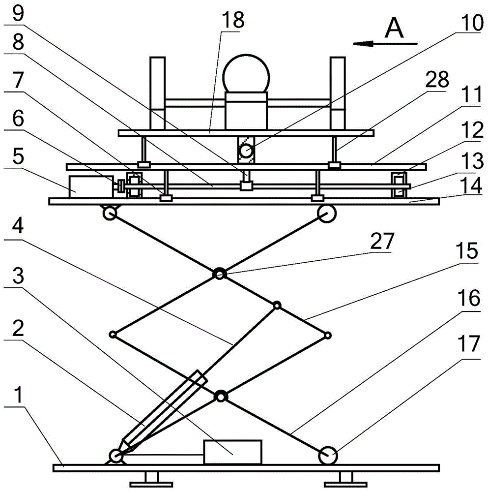
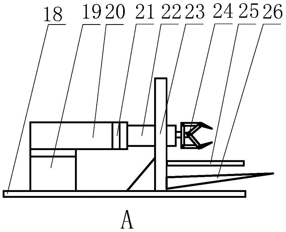
[0025] Such as figure 1 As shown, a multi-directional material automatic handling and loading equipment includes a vertical lifting platform, an X/Y horizontal feeding device and a loading and unloading workbench. The vertical lifting platform is used for vertical material handling and an X/Y horizontal feeding device It is used to realize the transportation of materials in the X/Y direction. The loading and unloading workbench is used for the placement and loading and unloading of materials. The X/Y horizontal feed device is installed on the vertical lifting platform. The loading and unloading workbench is installed on the X/Y horizontal feed. On the feeding device, there is a loading and unloading manipulator on the loading and unloading workbench.
[0026] Further, the vertical lifting platform includes a lifting platform base 1, a lifting platform hydraulic cylinder 2, a hydraulic pump 3, a lifting platform solenoid valve, a lifting platform hydraulic push rod 4, a lifting platform upper plate 14 and two sets of double fork brackets, The double-fork bracket is used to push the platform up and down. The two groups of double-fork brackets are distributed symmetrically in the front and rear. Each group of double-fork brackets includes a fixed bracket 15 and a movable bracket 16. The movable bracket 16 and the fixed bracket 15 are arranged crosswise, with connecting screws in the middle. 27 is hinged, the bottom of the movable bracket 16 is slidably connected to the slide rail on one side of the lifting platform base 1 through the bracket pulley 17, and the bottom of the fixed bracket 15 is hinged to the other end of the lifting platform base 1;
[0027] The hydraulic pump 3 and the lifting platform solenoid valve are respectively fixed and installed on the platform base 1 by bolts. The hydraulic pump 3 is connected to the lifting platform solenoid valve and the lifting platform hydraulic cylinder 2 respectively, and the lifting platform solenoid valve is connected to the PLC controller to control the platform. The lifting platform hydraulic cylinder 2 is hinged with one end of the lifting platform hydraulic push rod 4, the other end of the lifting platform hydraulic push rod 4 is hinged to the middle of the fixed bracket 15, and the tops of the fixed bracket 15 and the movable bracket 16 are respectively hinged on the lifting platform 上板面14 The bottom.
[0028] Further, the X/Y-direction horizontal feeding device includes a support platform 11, an X-direction ball screw drive device and a Y-direction ball screw drive device. The X-direction ball screw drive device consists of an X-direction ball screw 8. X-direction ball screw nut seat 9, X-direction bearing seat 12, X-direction bearing 13, X-direction coupling 6 and X-direction stepping motor 5, Y-direction ball screw drive device consists of Y-direction ball screw 10, Y-direction ball screw nut seat, Y-direction bearing seat, Y-direction bearing, Y-direction coupling and Y-direction stepper motor;
[0029] The support platform 11 is installed above the X-direction ball screw nut seat 9. The bottom of the support platform 11 is slidably connected to the guide rail on the upper plate surface 14 of the lifting platform through the first slider 7, and the X-direction ball screw 8 passes through the X-direction bearing 13 is installed between the X-direction bearing seats 12, and the X-direction bearing seat 12 is installed on the upper plate 14 of the lifting platform. The X-direction ball screw 8 is connected to the X-direction stepping motor 5 through the X-direction coupling 6. The stepping motor 5 is connected to the PLC controller, the Y-direction ball screw 10 is installed between the Y-direction bearing housings through the Y-direction bearing, the Y-direction bearing housing is installed on the support platform 11, and the end of the Y-direction ball screw passes through the Y direction. The coupling is connected with the Y-direction stepping motor, and the Y-direction stepping motor is connected with the PLC controller.
[0030] Further as figure 2 As shown, the loading and unloading workbench of this embodiment includes a work platform 18, a loading and unloading manipulator base 19, and a loading and unloading manipulator. The loading and unloading manipulator is installed on the loading and unloading manipulator base 19. The loading and unloading manipulator is divided into a wrist 21 and a claw 24. The wrist 21 is used for To realize the rotation action, one end of the wrist 21 is fixedly connected to the loading and unloading manipulator base 19 through the wrist rotary cylinder 20, the other end of the wrist 21 is fixedly connected to the claw 24 through the claw telescopic cylinder 22, and the loading and unloading manipulator base 19 is fixedly installed on the working platform 18, the bottom of the working platform 18 is slidably connected to the guide rail on the support platform 11 through the second sliding block 28.
[0031] Further, the loading and unloading workbench also includes a door frame 23, a baffle plate 25 and a fork frame 26. The bottom of the door frame 23 is fixedly installed on the work platform 18, and the door frame 23 is provided with a claw telescopic cylinder 22 through The claw telescopic cylinder 22 passes through the mast 23 and is fixedly connected to the claw 24, and the baffle 25 and the fork 26 are fixedly installed at the lower end of the mast 23, respectively.
[0032] The wrist rotary cylinder 20 in this embodiment is connected to a PLC controller through a wrist solenoid valve, and the claw telescopic cylinder 22 is connected to a PLC controller through a hand claw solenoid valve.
[0033] The fixed bracket 15 and the movable bracket 16 in this embodiment are both V-shaped brackets, and the two V-shaped brackets are arranged crosswise, and the intersection of the V-shaped brackets is hinged by two connecting screws 27 respectively.
[0034] The solenoid valve of the lifting platform in this embodiment adopts a double-coil double-position solenoid valve.
[0035] Such as image 3 As shown, the present invention uses a PLC controller to connect the lifting platform solenoid valve, X-direction stepping motor 5, Y-direction stepping motor, wrist solenoid valve and claw solenoid valve respectively. The lifting platform solenoid valve is connected to the hydraulic pump 3 to control the vertical The lifting table moves up and down; X-direction stepping motor 5 is connected to X-direction ball screw 8, Y-direction stepping motor is connected to Y-direction rolling to lead screw 10 to control the horizontal movement of the loading and unloading table; wrist solenoid valve is connected to wrist rotary cylinder 20 , The claw solenoid valve is connected to the claw telescopic cylinder 22 to control the installation and loading and unloading of materials by the loading and unloading manipulator.
[0036] The working process of the multi-directional automatic material handling loading and unloading equipment of the present invention is:
[0037] S1: Multi-directional automatic material loading and unloading equipment is started, and various working parameters of the equipment under different working conditions are set;
[0038] S2: Place the materials to be loaded and unloaded on the fork 26 of the loading and unloading table to complete the material clamping;
[0039] S3: The vertical lifting platform starts to lift the material to the designated position;
[0040] S4: The X/Y direction horizontal feed mechanism is activated to move the material to the designated position;
[0041] S5: The loading and unloading manipulator starts, the equipment adjusts the position so that the manipulator is in the designated position, the manipulator claw grips the material, and the manipulator wrist rotates to adjust the material to the proper position. After installation, the manipulator claw and wrist return to the initial state;
[0042] S6: The equipment moves to the next designated position to complete the handling and installation of the next material;
[0043] S7: After completing all the material installation tasks, the PLC controller will carry out the unloading action after the set time period. The unloading action is in the opposite order of the installation action.
[0044] S8: After completing the handling and loading and unloading of all materials, the equipment is shut down and stops working.
[0045] Those of ordinary skill in the art will realize that the embodiments described herein are to help readers understand the principles of the present invention, and it should be understood that the protection scope of the present invention is not limited to such special statements and embodiments. Those of ordinary skill in the art can make various other specific modifications and combinations that do not depart from the essence of the present invention based on the technical enlightenment disclosed in the present invention, and these modifications and combinations still fall within the protection scope of the present invention.

PUM

no PUM

Description & Claims & Application Information

We can also present the details of the Description, Claims and Application information to help users get a comprehensive understanding of the technical details of the patent, such as background art, summary of invention, brief description of drawings, description of embodiments, and other original content. On the other hand, users can also determine the specific scope of protection of the technology through the list of claims; as well as understand the changes in the life cycle of the technology with the presentation of the patent timeline. Login to view more.

Similar technology patents

Classification and recommendation of technical efficacy words

  • Simple structure
  • Easy to implement

Beam expanding optical element, beam expansion method, image display apparatus, and head-mounted display

InactiveUS20070188837A1Reduce color unevennessSimple structureOptical light guidesSubstrate with hologramHead worn displayLight wave
Owner:KONICA MINOLTA INC

Microlithographic projection exposure apparatus

InactiveUS20050068499A1Simple structureReliable and low-maintenance operationProjectorsPhotomechanical exposure apparatusCamera lensPhysics
Owner:CARL ZEISS SMT GMBH
Why Eureka
Try Eureka