
Combined type mechanical crushing centrifugal pelletization device

A technology of mechanical crushing and centrifugal granulation, which is applied in the direction of recycling technology, etc., can solve the problems of low granulation percentage, large granulation particles, unfavorable heat exchange between particles and air, etc., and achieve an increase in granulation ratio, fine and uniform particles, Effect of increasing the throughput of slag

Active Publication Date: 2015-01-28
CHONGQING UNIV
View PDF8 Cites 22 Cited by
  • Summary
  • Abstract
  • Description
  • Claims
  • Application Information

AI Technical Summary

Problems solved by technology

In the traditional rotor granulation process, the blast furnace slag forms liquid droplets and liquid filaments under the action of centrifugal force. When the flow rate continues to increase, a liquid film is formed. The granulated particles obtained at this time are relatively large, which is not conducive to the separation of particles and heat exchange of air
The liquid silk and liquid film outside the granulator are easy to exchange heat with the air and solidify, resulting in "cotton slag" and lumps in the granulated product, and the granulation percentage is low
The above problems greatly limit the application of blast furnace slag dry heat recovery process

Method used


Image

  • Combined type mechanical crushing centrifugal pelletization device
  • Combined type mechanical crushing centrifugal pelletization device
  • Combined type mechanical crushing centrifugal pelletization device

Examples


Embodiment Construction

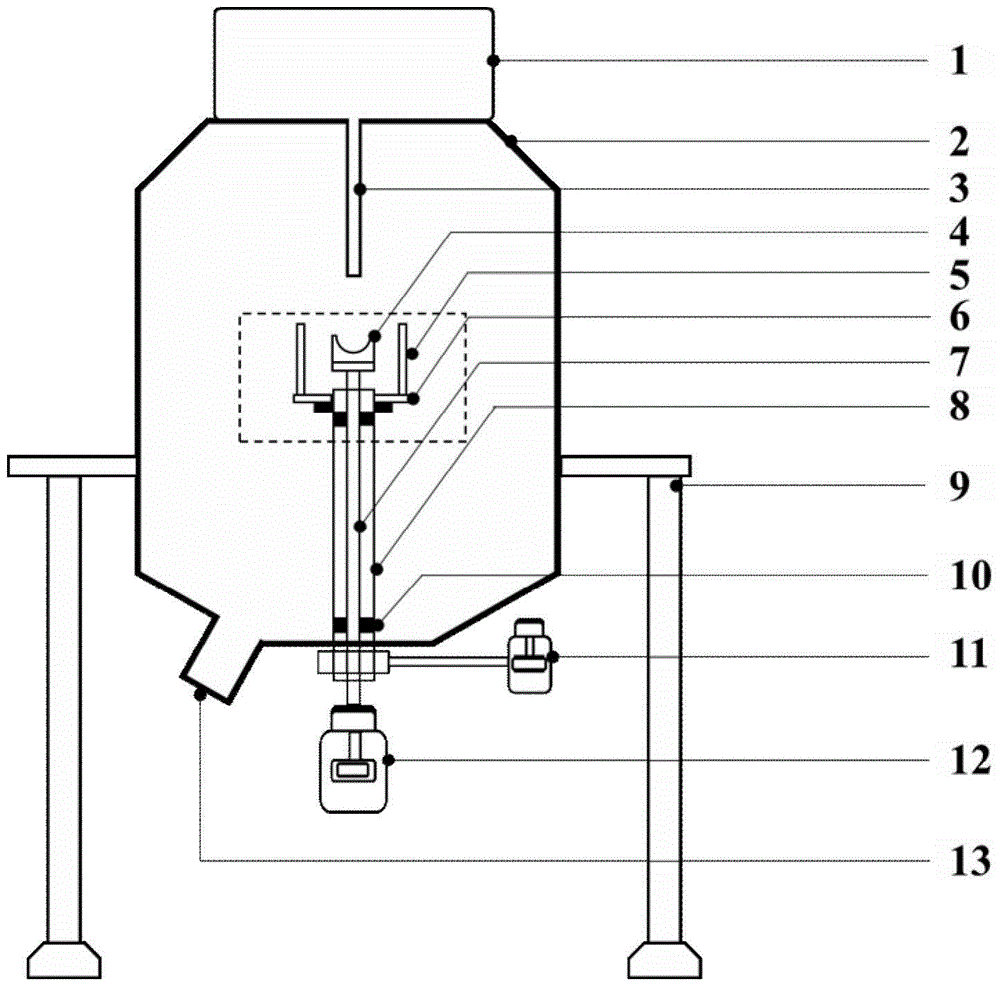
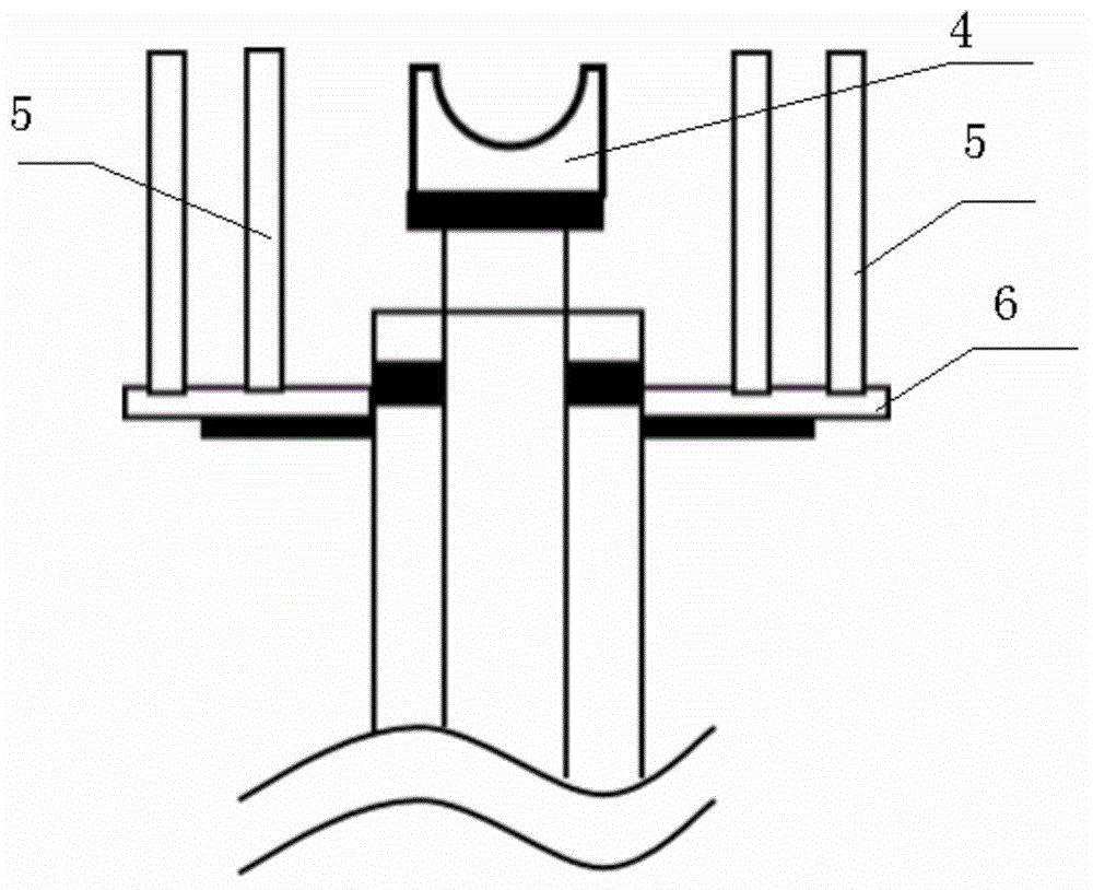
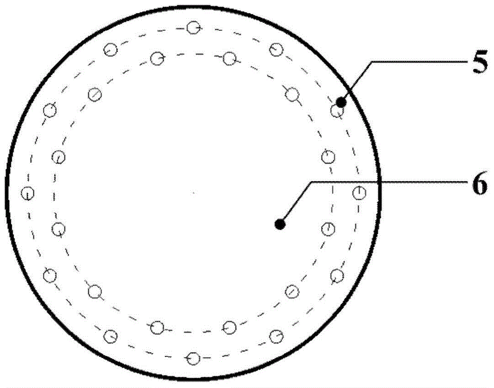
[0017] see Figure 1 to Figure 4 , a combined mechanical crushing and centrifugal granulation device, including a storage bin 1, a feed port 3 located at the lower part of the storage bin 1, a granulation bin 2, and a discharge port 13 located at the lower part of the granulation bin 2; the feed port 3 and the The storage bin 1 is connected, and the granulation bin 2 is fixed by the support column 9; a rotor 4 is arranged in the granulation bin 2, and the rotor 4 is located below the injection port 3, and the rotor 4 is fixedly sleeved On the inner rotating shaft 7, the inner rotating shaft 7 is passed through the hollow rotating shaft 8, and the inner rotating shaft 7 is driven by a motor one 12, the hollow rotating shaft 8 is supported by the inner rotating shaft 7 through a bearing 10, and the hollow rotating shaft 8 Driven by motor two 11; a rotating disc 6 is set below the rotor 4, and the rotating disc 6 is fixedly sleeved on the hollow shaft 8; a crushing blade is arran...


PUM


Abstract

The invention discloses a combined type mechanical crushing centrifugal pelletization device which comprises a slag storage cabin, a feeding hole, a pelletization cabin and a slag outlet, wherein the feeding hole is formed in the lower part of the slag storage cabin; the slag outlet is formed in the lower part of the pelletization cabin; the feeding hole is communicated with the slag storage cabin; the pelletization cabin is fixed through a support column. The combined type mechanical crushing centrifugal pelletization device is characterized in that a rotating cup is arranged inside the pelletization cabin; the rotating cup is positioned below the feeding hole; the rotating cup fixedly sleeves an inner rotating shaft; the inner rotating shaft is arranged on a hollow rotating shaft in a penetration manner; the inner rotating shaft is driven by a motor I; the hollow rotating shaft is supported by the inner rotating shaft through a bearing; the hollow rotating shaft is driven by a motor II; a rotating disc is arranged below the rotating cup; the rotating disc fixedly sleeves the hollow rotating shaft; crushing cutters are arranged on the rotating disc along the circumference; the crushing cutters are positioned on the outer side of the rotating cup. By adopting a method that the rotating cup is combined with the rotating disc, the molten slag treatment capacity of a single pelletizer is greatly increased, and thus the combined type mechanical crushing centrifugal pelletization device can be widely used in the fields of steel, metallurgy and the like.

Description

technical field [0001] The invention relates to a high-temperature molten material granulator, in particular to a combined mechanical crushing and centrifugal granulation device. Background technique [0002] Blast furnace slag is the main by-product in the steel production process, the discharge temperature is between 1400 and 1550 °C, and each ton of blast furnace slag contains 1260×10 sensible heat 3 ~1880×10 3 kJ, equivalent to the calorific value of 60kg standard coal. The treatment of blast furnace slag is mainly water quenching method, but it will cause many disadvantages: a large amount of water resources are wasted, sulfide is easily formed, the formed alkali metal solution pollutes water sources, and the heat carried by blast furnace slag is not recovered. In this context, the dry granulation heat recovery process has attracted the attention of researchers. In the dry granulation heat recovery process, obtaining uniform and fine slag particles is the basis for he...

Claims


Application Information

Patent Timeline
IPC IPC(8): C21B3/06
CPCC21B3/06C21B2200/00Y02W30/50
Inventor 朱恂吴君军王宏廖强丁玉栋李俊陈蓉叶丁丁黄云
Owner CHONGQING UNIV
Learn More