Dry granulation waste heat recovery system

A waste heat recovery system and waste heat recovery technology, applied in the field of waste heat recovery system, can solve the problems of low quality of hot air, low utilization value, etc. Effect

Active Publication Date: 2016-08-24
CHONGQING UNIV
View PDF6 Cites 0 Cited by
  • Summary
  • Abstract
  • Description
  • Claims
  • Application Information

AI Technical Summary

Problems solved by technology

However, the air in this method has only gone through the heat exchange process of the fluidized bed once, and the quality of the obtained hot air is not high, and the utilization value is low.

Method used


Image

  • Dry granulation waste heat recovery system
  • Dry granulation waste heat recovery system
  • Dry granulation waste heat recovery system

Examples


Embodiment Construction

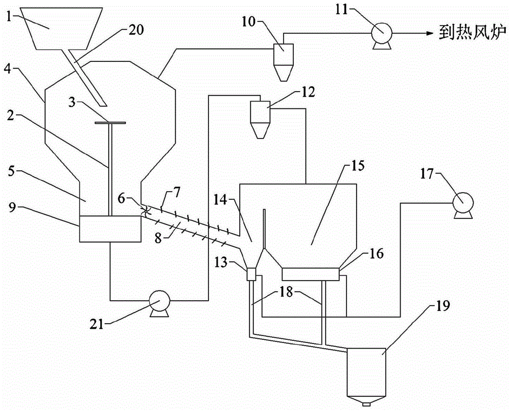
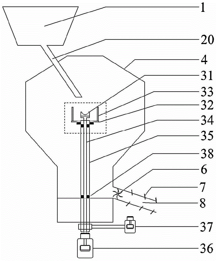
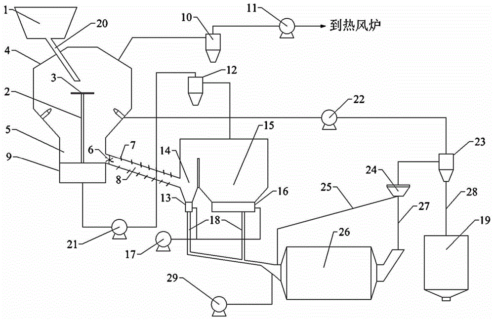
[0026] see Figure 1 to Figure 4, The waste heat recovery system for dry granulation treatment includes a slag storage bin 1, a granulation cooling unit 4, a first-level waste heat recovery unit 5, a second-level waste heat recovery unit 14, and a third-level waste heat recovery unit 15; the slag storage bin 1 passes The injection pipe 20 communicates with the granulation cooling unit 4; it is characterized in that: the top of the granulation cooling unit 4 is provided with a first air outlet, and the first air outlet is connected to a high-temperature booster fan 11 through a pipeline; A granulator 3 is arranged in the granulation cooling unit 4, and the granulator 3 is located below the injection pipe 20, and is driven to rotate by the rotating shaft 2; the first-stage waste heat recovery unit 5 is arranged below the granulation cooling unit 4, The bottom of the primary waste heat recovery unit 5 is provided with a first fluidized bed 9 and a slag discharge pipe 8, and the s...


PUM


Abstract

The invention discloses a dry-type granulation treatment waste heat recovery system which comprises a slag storage bin, a granulation cooling unit, a primary waste heat recovery unit, a secondary waste heat recovery unit and a tertiary waste heat recovery. The system is characterized in that the top of the granulation cooling unit is provided with a first air outlet; the first air outlet is connected with a high-temperature booster fan through a pipeline; a granulator is arranged in the granulation cooling unit, positioned below a charging pipe and driven by a rotating shaft to rotate; the primary waste heat recovery unit is arranged below the granulation cooling unit; the bottom of the primary waste heat recovery unit is provided with a first fluidized bed and a slag discharge pipe; the slag discharge pipe is communicated with the secondary waste heat recovery unit; the bottom of the secondary waste heat recovery unit is provided with a spray bed; and the upper part of the secondary waste heat recovery unit is communicated with the upper part of the tertiary waste heat recovery unit. The system implements the dry-type granulation function and high-efficiency waste heat recovery, and can be widely used in the fields of steel, metallurgy and the like.

Description

technical field [0001] The invention relates to a waste heat recovery system, in particular to a dry granulation treatment waste heat recovery system. Background technique [0002] Blast furnace slag is a by-product formed by gangue in ore, ash in fuel and non-volatile components in flux during the blast furnace smelting process. The main components of blast furnace slag are CaO and SiO 2 、A1 2 o 3 , Fe 2 o 3 , MgO, MnO, TiO 2 etc. In 2013, my country's pig iron output was about 750 million tons. Even if 0.3 tons of slag was produced for every ton of pig iron produced, the blast furnace slag output was about 225 million tons. The temperature of the blast furnace slag is about 1500°C, the heat contained in 1 ton of blast furnace slag is equivalent to 64kg of standard coal, and the heat in the blast furnace slag produced throughout the year is equivalent to 1.44×10 7 t standard coal, if the heat in the blast furnace slag can be utilized, considerable energy saving benefi...

Claims


Application Information

Patent Timeline
Patent Type & Authority Patents(China)
IPC IPC(8): C21B3/08C21B3/06
CPCC04B5/00C21B3/06C21B3/08F27D17/004Y02W30/50
Inventor 朱恂谭煜王宏吴君军廖强丁玉栋李俊叶丁丁黄云
Owner CHONGQING UNIV
Why Eureka
Try Eureka