Pavement roughness detection system and method

A detection system and flatness technology, applied in roads, roads, road repair, etc., can solve problems such as large shrinkage ratio of concrete, decreased road surface flatness, and inconvenient use.

Inactive Publication Date: 2015-01-28
RES INST OF HIGHWAY MINIST OF TRANSPORT
View PDF4 Cites 22 Cited by
  • Summary
  • Abstract
  • Description
  • Claims
  • Application Information

AI Technical Summary

Problems solved by technology

For example, in the construction process of formwork paving with large-thickness cement concrete slabs, due to the limited power of the vibrating rod, it is easy to vibrate unevenly between the upper and lower layers of the concrete slab, resulting in a large difference in the density of the upper and lower slabs
In addition, the DBI (Dowel Bar Inserting) device extrudes the extruded concrete during the insertion process of the dowel bar. Since the surrounding concrete cannot flow to fill the empty groove, the road surface is leveled and In the process of smoothing the road surface with super trowels, only mortar can fill the empty grooves, resulting in aggregate segregation, making...

Method used


Image

  • Pavement roughness detection system and method
  • Pavement roughness detection system and method
  • Pavement roughness detection system and method

Examples


Embodiment 1

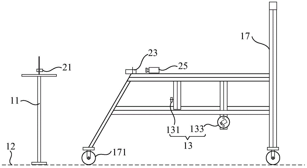
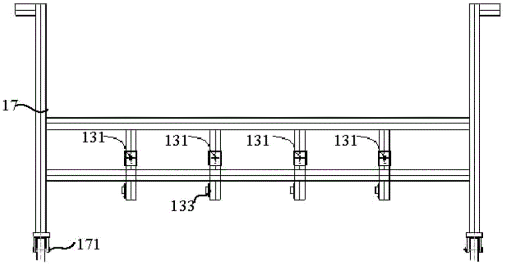
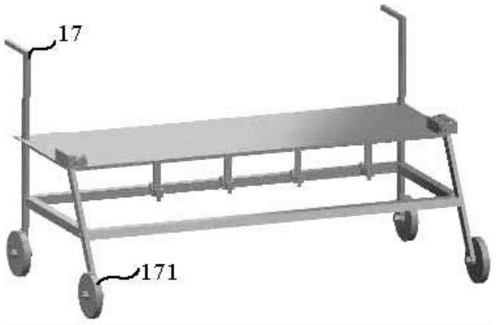
[0055] Figure 1a and Figure 1b It is a schematic structural diagram of the road surface smoothness detection system according to the first embodiment of the present invention, as shown in Figure 1a and Figure 1b As shown, the road surface smoothness detection system may mainly include:

[0056] At least one reference target 11 is arranged above the road surface 12 to be measured;

[0057] at least one linear structured light sensor 13, used for projecting linear structured light to the road surface 12 to be measured, and capturing a light bar image formed by the linear structured light on the road surface 12 to be measured;

[0058] A computing device (not shown in the figure), connected with the line structured light sensor 13 , converts the light bar image received from the line structured light sensor 13 into three-dimensional data, and analyzes the data according to the reference target 11 The three-dimensional data of the road surface to be measured is corrected, ...

Embodiment 2

[0065] Figure 4 It is a schematic structural diagram of the pavement flatness detection system according to the second embodiment of the present invention, Figure 4 shown with Figure 1a , Figure 1b , figure 2 , image 3 Components with the same label have the same meaning and will not be repeated here. like Figure 4 As shown in the figure, the main difference from the above-mentioned embodiment is that, in this road surface flatness detection system, a rangefinder 31 is set on the mobile measuring bridge 17, and a range finder 31 is set on the reference target 11 corresponding to the position of the rangefinder 31. the target board 33; the rangefinder 31 is used to project laser light to the target board 33 on the reference target 11, and receive the laser light returned from the target board 33 to measure the movement of the measurement bridge 17 and the The distance between the reference targets 11 is sent to the computing device so that the computing device can ...

Embodiment 3

[0071] Figure 5 It is a flow chart of the road surface smoothness detection method according to the third embodiment of the present invention, such as Figure 5As shown, the road surface smoothness detection method can use any structure of the road surface smoothness detection system in the above-mentioned embodiments to detect the smoothness of the road surface to be measured, and the method may specifically include:

[0072] Step 101, using the first CCD to capture the light strip image formed by the line structured light emitted by the line structured light sensor on the road surface to be measured;

[0073] Step 102, converting the light bar image into three-dimensional data of the road surface to be measured;

[0074] Step 103, correcting the three-dimensional data of the road surface to be measured according to the reference target;

[0075] Step 104: Determine the smoothness of the road surface to be measured according to the corrected three-dimensional data.

[007...


PUM


Abstract

The invention relates to a pavement roughness detection system and method, wherein the system comprises at least one reference target, arranged above a to-be-measured pavement; at least one line structured light sensor, used for casting line structured light to the to-be-measured pavement and shooting a light bar image of the line structured light, formed on the to-be-measured pavement; and a computing device, connected with the line structured light sensor; the computing device converts the light bar image received from the line structured light sensor into three-dimensional data, according to the reference target, the three-dimensional data of the to-be-measured pavement is modified, and according to the modified three-dimensional data, the roughness of the to-be-measured pavement is determined. By use of the line structured light sensor for capturing the light bar image of the to-be-measured pavement, then the light bar image is converted into the three-dimensional data, according to the reference target, the three-dimensional data of the to-be-measured pavement is modified, and the roughness of the to-be-measured pavement can be conveniently and accurately determined.

Description

technical field [0001] The invention relates to the field of highway road surface detection, in particular to a road surface smoothness detection system and method. Background technique [0002] In the process of pavement construction, there are many factors that affect the smoothness of the pavement. For example, in the process of form paving with slippery slabs of large-thickness cement concrete, due to the limited power of the vibrating rod, it is easy to cause uneven vibrating of the upper and lower layers of the concrete panel, resulting in a large difference in the density of the upper and lower slabs. In addition, the DBI (Dowel Bar Inserting, Dowel Bar Inserting) device extrudes the extruded concrete during the insertion of the dowel bar. Since the surrounding concrete cannot flow and fill the empty grooves, the road surface is leveled and smoothed by the use of leveling beams. In the process of troweling the road surface with the super trowel, only the mortar can f...

Claims


Application Information

Patent Timeline
IPC IPC(8): E01C23/01
CPCE01C23/01
Inventor 刘英田波彭鹏谢晋德
Owner RES INST OF HIGHWAY MINIST OF TRANSPORT
Why Eureka
Try Eureka