
One-piece type pipeless massage pump with intermediate water spraying in water-collection vortex flow

A one-piece, eddy current technology, applied to parts of pumping devices for elastic fluids, non-variable pumps, pumps, etc., can solve the problems of impeller loss, insufficient concentration of water outlet, insufficient water outlet force, etc., to reduce Loss, energy-saving massage, high water output effect

Active Publication Date: 2015-01-28
JIANGMEN CITY SHUO TAI ELECTRIC CO LTD
View PDF7 Cites 4 Cited by
  • Summary
  • Abstract
  • Description
  • Claims
  • Application Information

AI Technical Summary

Problems solved by technology

Due to the structural characteristics of the impeller structure and the water chamber of the pump body of the pipeless massage pump of the existing structure, this kind of pipeless massage pump adopts the above-mentioned water outlet method. When the water is discharged, the high-speed water will continuously hit the friction pipeless massage pump The side wall of the pump body will cause wear and tear on the side wall of the pump body and reduce the service life; and when the impeller of this structure rotates to form a high-speed water flow, it also needs to hit the high-speed water flow on the side wall of the pump body, which will also affect the impeller. A certain loss is generated; while the water outlet of the existing pipeless massage pump mainly enters the water on the side wall of the water surface cover, the water outlet is not concentrated enough, and even if the water is discharged on the front of the surface cover, there is still not concentrated water outlet, the process consumes a lot of water, and the water outlet Insufficient strength and many other defects, its efficiency is not efficient enough
Because the pipeless massage pump structure of the prior art determines that the existing water outlet methods cannot be concentrated in one place, etc.
[0003] In addition, the pump body of the traditional ductless massage water pump is composed of a split structure, such as figure 1 Shown; Existing pipeless massage water pump consists of face cover 11, filter screen (water retaining cover) 21, water guide cover 31, impeller 41, front pump body 51, screw cap 61, rear pump body 71 successively from top to bottom and other components, the water inlet and outlet methods of the water pump of this structure are the middle water inlet and the side wall outlet. The composition of the pump body is composed of the front pump body and the rear pump body. The rear pump body cannot be a one-piece structure, let alone integrally formed. It must be a split structure and assembled after each part is produced separately.
The water cavity of the ductless massage pump with this structure is separated from the motor rotor, and the rubber ring is used to seal each other, so that the motor will inevitably vibrate when it is working, and the long-term continuous extrusion of the rubber ring caused by the vibration will accelerate the rubber ring. Aging, coupled with the aging cracks caused by the long-term direct contact of the rubber ring with cold and hot water impact, etc., resulting in seal leakage and other disadvantages; and this split structure also has coordination problems with the installation dimensions of the various parts of the pump body, and the production accuracy requires High and increase the difficulty of production

Method used


Image

  • One-piece type pipeless massage pump with intermediate water spraying in water-collection vortex flow
  • One-piece type pipeless massage pump with intermediate water spraying in water-collection vortex flow
  • One-piece type pipeless massage pump with intermediate water spraying in water-collection vortex flow

Examples


Embodiment 1

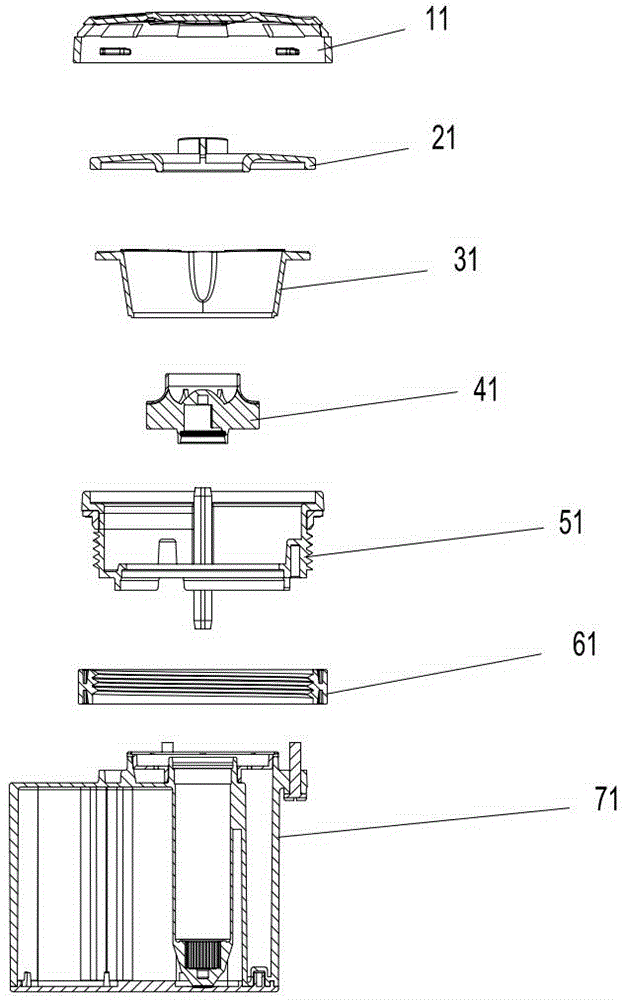
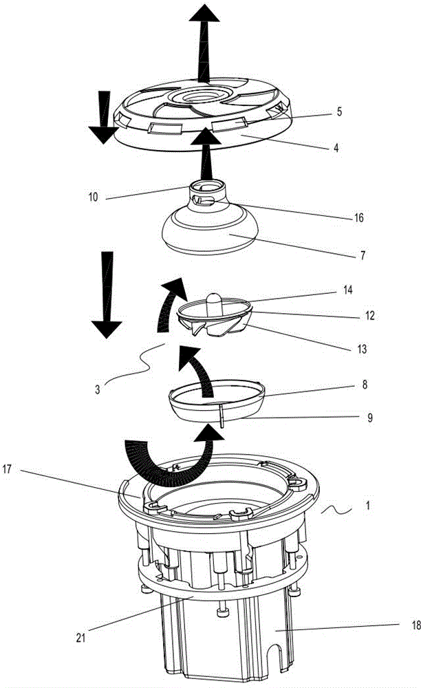
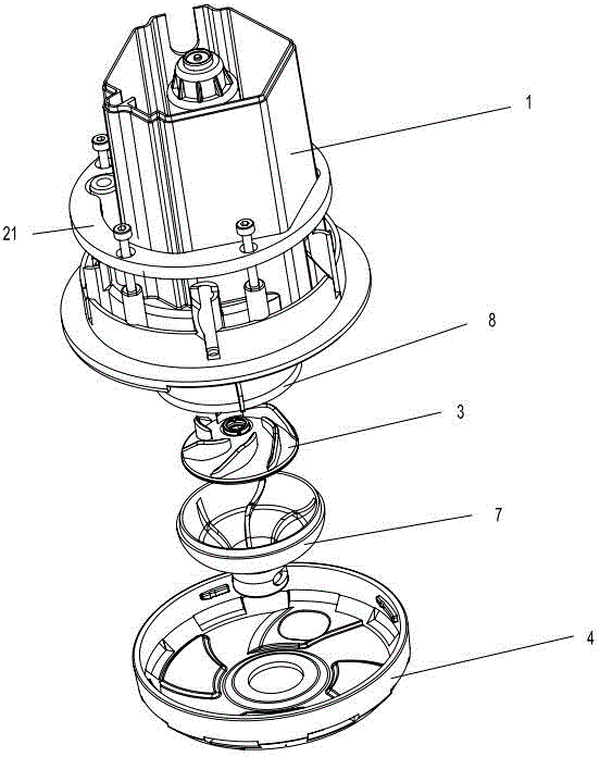
[0020] A kind of water-gathering vortex in the middle of the embodiment of the present invention sprays water one-piece pipeless massage pump, such as figure 2 , image 3 , Figure 4 and Figure 5As shown, it includes the pump body 1, the motor 2 installed in the pump body and at the bottom, the impeller 3 driven by the motor, the cover 4 and the water inlet 5 arranged on the cover, and the cavity formed by the pump body and the cover. The body is provided with a water guide assembly 6, the impeller is placed in the water outlet water guide chamber formed in the water guide assembly, the water inlet 9 of the water outlet water guide chamber is located at the bottom of the water guide assembly, and the top of the water guide assembly is provided with a water guide chamber water outlet 10 As outlet for ductless massage pumps. The pump body is a one-piece structure composed of a front pump body cavity 17 and a rear pump body cavity 18 and is integrally formed. The front end o...


PUM


Abstract

The invention discloses a one-piece type pipeless massage pump with intermediate water spraying in a water-collection vortex flow. The one-piece type pipeless massage pump comprises a pump body, a motor, an impeller, a surface cover and a water inlet formed in the surface cover, wherein a water guide assembly is arranged in a water cavity formed by the pump body and the surface cover, the impeller is arranged in a water outlet water guide cavity formed by the water guide assembly, the water flow inlet of the water outlet water guide cavity is formed in the bottom of the water guide assembly, and a water guide cavity water flow outlet formed in the top of the water guide assembly serves as the water outlet of the pipeless massage pump; the pump body is integrally formed by a one-piece type structure consisting of a front pump body cavity and a rear pump body cavity, a water cavity body for mounting the impeller and the water guide assembly is arranged at the front end of the pump body, and a motor cavity for mounting the motor is arranged at the rear end of the pump body; a plastic plate arranged between the water cavity body of the pump body and the motor cavity body is used for separating the pump body into a front cavity body and a rear cavity which are independently connected; a mounting positioning ring with three or more than three clamp nut opening and closing guiding plates is arranged at the periphery of the front pump body cavity.

Description

technical field [0001] The invention relates to a pipeless massage pump, in particular to a one-piece pipeless massage pump with a water collecting vortex in the middle and spraying out from a turbine. Background technique [0002] At present, traditional ductless pumps, especially ductless massage pumps, generally use the way of water outlet on the side of the cover and water intake in the middle of the front to realize the normal water inlet and outlet functions of the ductless massage pump. The water outlet distribution adopts multiple water outlets on the side of the cover, and multiple water inlets are distributed in the middle of the front. Due to the structural characteristics of the impeller structure and the water chamber of the pump body of the pipeless massage pump of the existing structure, this kind of pipeless massage pump adopts the above-mentioned water outlet method. When the water is discharged, the high-speed water will continuously hit the friction pipele...

Claims


Application Information

Patent Timeline
Patent Type & Authority Applications(China)
IPC IPC(8): F04D29/42F04D29/44F04D29/08
CPCF04D13/0606F04D29/086F04D29/426F04D29/445
Inventor 石泰山
Owner JIANGMEN CITY SHUO TAI ELECTRIC CO LTD
Features
  • Generate Ideas
  • Intellectual Property
  • Life Sciences
  • Materials
  • Tech Scout
  • Unparalleled Data Quality
  • Higher Quality Content
  • 60% Fewer Hallucinations
Learn More