Eureka AIR delivers breakthrough ideas for toughest innovation challenges, trusted by R&D personnel around the world.

Liquid constant pressure source device

A constant pressure source and liquid technology, which is applied in the field of hydraulic constant pressure devices, can solve the problems of large liquid pressure fluctuations, low stability accuracy, and mutual solubility of liquid and gas, and achieve the elimination of liquid pressure fluctuations, high stability and accuracy, and prevent liquid The effect of miscibility with gas

Active Publication Date: 2016-08-31
LIUZHOU YUANCHUANG EFI TECH
View PDF10 Cites 0 Cited by
  • Summary
  • Abstract
  • Description
  • Claims
  • Application Information

AI Technical Summary

Problems solved by technology

Existing liquid pressure stabilizing device, as publication number is a kind of liquid stabilizing device disclosed by CN1385622A, although this device can provide relatively stable output pressure, its integral volume is bigger, and precision is lower, and has used computer, PLC , frequency conversion motor, etc., the control structure is more complicated, and the cost is relatively high; in addition, there are also liquid voltage stabilizing devices, such as the authorized announcement number CN200964346Y "Large Infusion Filling Constant Pressure Device with Stable Filling Volume", the structure is relatively simple , but the liquid and gas in the liquid storage tank of the device are not isolated, and it is easy to make the liquid and gas miscible; and the liquid pressure fluctuates greatly, and the stability accuracy is low

Method used


Image

  • Liquid constant pressure source device
  • Liquid constant pressure source device
  • Liquid constant pressure source device

Examples


Embodiment 1

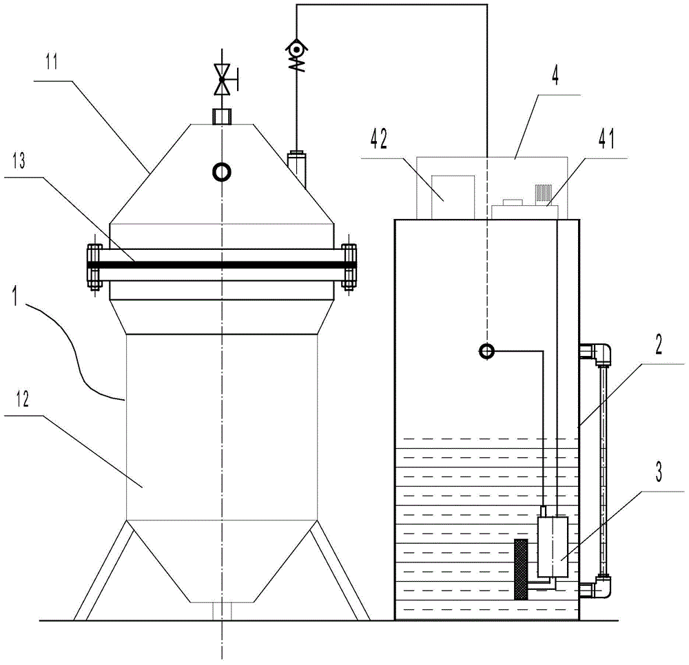
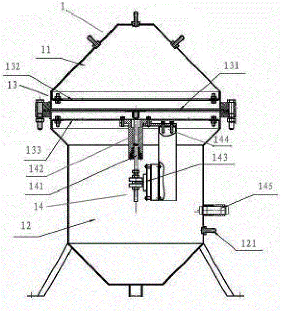
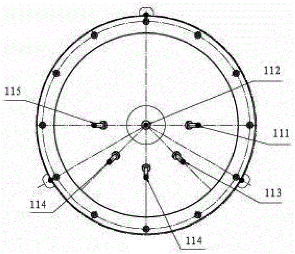
[0027] figure 1 Disclosed in is a kind of liquid constant pressure source device, comprises surge tank 1, oil tank 2, hydraulic pump 3, control box 4, is provided with single-chip microcomputer 41 and power supply 42 thereof in the control box 4, the output end of single-chip microcomputer 41 and hydraulic pump 3, the described surge tank 1 includes an upper tank body 11 and a lower tank body 12 connected together (see Figure 2 ~ Figure 3 ), the upper tank 11 communicates with the oil tank 2 through the oil pipe, the inner cavity of the upper tank 11 forms a liquid storage chamber, the lower tank 12 communicates with the compressed air source through the air inlet, and the inner cavity of the lower tank 12 Form an air storage chamber, a rubber isolation device 13 is installed between the upper tank body 11 and the lower tank body 12, and a pressure detection device 14 is installed on the rubber isolation device 13, the output end of the pressure detection device 14 is connect...


PUM


Abstract

The invention relates to a constant-pressure hydraulic device, in particular to a liquid constant-pressure source device. The liquid constant-pressure source device comprises a surge tank, an oil tank, a hydraulic pump and a control box. A single-chip microcomputer and a power source thereof are arranged in the control box, and an output end of the single-chip microcomputer is connected with an input end of the hydraulic pump. The surge tank comprises an upper tank body and a lower tank body, the upper tank body and the lower tank body are connected together, the upper tank body is communicated with the oil tank through an oil pipe, a liquid storage chamber is formed in an inner cavity of the upper tank body, the lower tank body is communicated with a compressed air source through an air inlet, and an air storage chamber is formed in an inner cavity of the lower tank body. A pressure detection device is mounted on a rubber isolation device which is mounted between the upper tank body and the lower tank body, and an output end of the pressure detection device is connected with an input end of the single-chip microcomputer. Mutual dissolution of liquid and air can be prevented, and instant liquid pressure wave action generated during pressure changes can be eliminated. In addition, the liquid constant-pressure source device has the advantages of high liquid pressure stabilization precision, simple structure, small size and low production cost.

Description

technical field [0001] The invention relates to a hydraulic constant pressure device, in particular to a liquid constant pressure source device. Background technique [0002] In the industrial field, it is usually necessary to stabilize the pressure of the medium in the pressure vessel to meet the high-precision requirements for stable output pressure when the equipment is working, and the liquid constant pressure device is a device for stabilizing the pressure of the medium in the pressure vessel. a device. Existing liquid pressure stabilizing device, such as publication number is a kind of liquid stabilizing device disclosed by CN1385622A, although this device can provide relatively stable output pressure, its integral volume is bigger, and precision is lower, and has used computer, PLC , frequency conversion motor, etc., the control structure is more complicated, and the cost is relatively high; in addition, there are liquid voltage stabilizing devices, such as the autho...

Claims


Application Information

Patent Timeline
Patent Type & Authority Patents(China)
IPC IPC(8): F15B5/00
CPCF15B5/00
Inventor 唐凤君黎艺文
Owner LIUZHOU YUANCHUANG EFI TECH
Why Eureka
Eureka Blog
Learn More