System and method for cooling gas compressor inlet gas

A technology of gas compressor and imported gas, which is applied in the system field of cooling gas compressor imported gas, and can solve the problem of the method and system of waste heat after the compressor stage does not exist

Active Publication Date: 2015-01-28
XECA TURBO TECH (BEIJING) CO LTD
View PDF6 Cites 5 Cited by
  • Summary
  • Abstract
  • Description
  • Claims
  • Application Information

AI Technical Summary

Problems solved by technology

[0006] In summary, it can be seen that there is no method and system that can effectively utilize the post-stage waste heat of the compressor in the prior art

Method used


Image

  • System and method for cooling gas compressor inlet gas
  • System and method for cooling gas compressor inlet gas
  • System and method for cooling gas compressor inlet gas

Examples


Embodiment 1

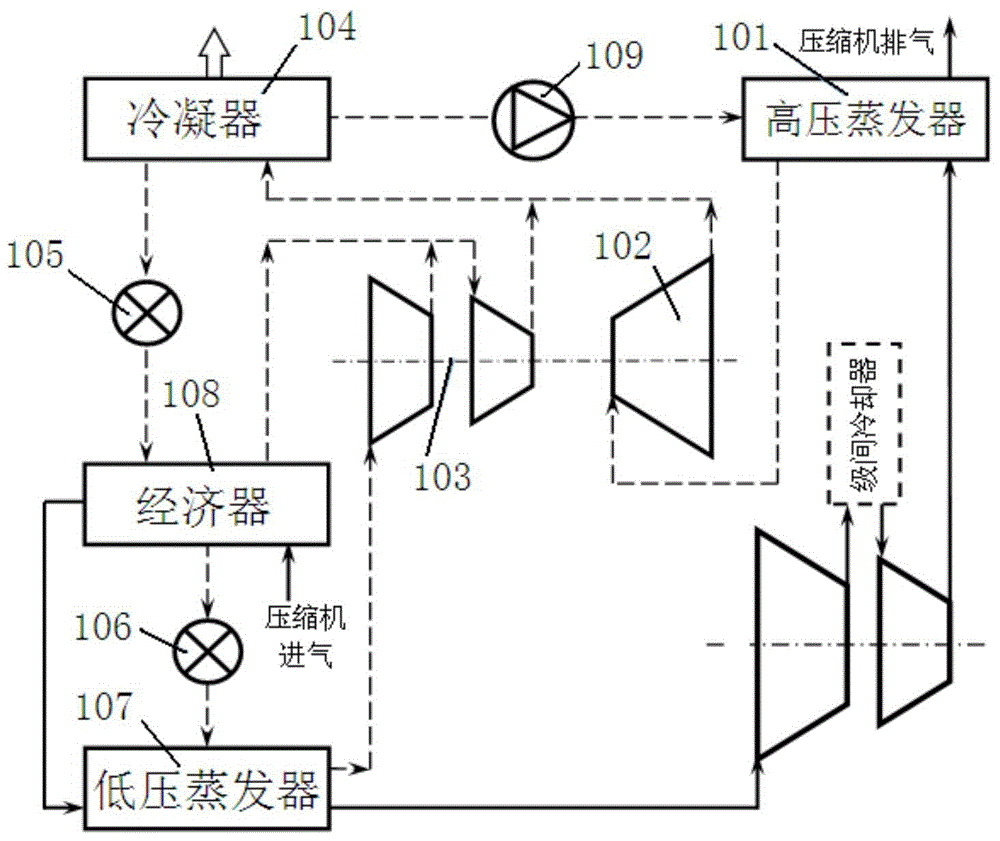
[0074] refer to figure 1 , this embodiment provides a system for cooling the inlet gas of a gas compressor, including a high-pressure evaporator 101, an ORC turbine 102, an ORC compressor 103, a condenser 104, a high-pressure pressure relief valve 105, a low-pressure pressure relief valve 106, a low-pressure Evaporator 107, economizer 108 and booster pump 109; said high pressure and low pressure mean the fluid pressure through said evaporator or pressure reducing valve or distinguish technical terms;

[0075] The high-pressure evaporator 101, the low-pressure evaporator 107, and the economizer 108 all include a refrigerant inlet, a refrigerant outlet, a cooled medium inlet, and a cooled medium outlet; the cooled medium is the working fluid of the gas compressor, Can be air or other gases;

[0076] The condenser 104 includes a refrigerant inlet, a refrigerant outlet, a cooling medium inlet and a cooling medium outlet; the cooling medium may be ambient water, so as to discharge...

Embodiment 2

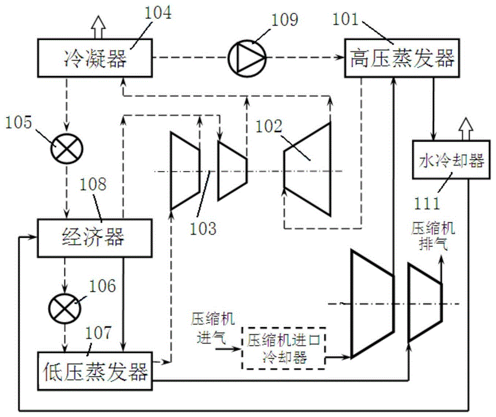
[0096] refer to figure 2 , this embodiment provides a system for cooling the inlet gas of a multi-stage gas compressor, including a high-pressure evaporator 101, an ORC turbine 102, an ORC compressor 103, a condenser 104, a high-pressure pressure reducing valve 105, and a low-pressure pressure reducing valve 106 , low-pressure evaporator 107, economizer 108, booster pump 109 and water cooler 111;

[0097] The high-pressure evaporator 101, the low-pressure evaporator 107, and the economizer 108 all include a refrigerant inlet, a refrigerant outlet, a cooled medium inlet, and a cooled medium outlet;

[0098] The condenser 104 includes a refrigerant inlet, a refrigerant outlet, a cooling medium inlet and a cooling medium outlet;

[0099] The water cooler 111 includes a cooled medium inlet, a cooled medium outlet, a cooling medium inlet and a cooling medium outlet;

[0100] The inlet of the cooled medium of the high-pressure evaporator 101 is connected to the stage outlet of th...

Embodiment 3

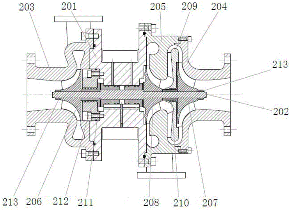
[0119] refer to image 3 , this embodiment provides an ORC integrated turbine refrigeration compressor, including an intermediate body 201, a main shaft 202, a turbine volute 203, a primary volute 204, a secondary volute 205, a turbine impeller 206, a primary impeller 207, Secondary impeller 208, intermediate partition 209, shaft sleeve 210, thrust disc 211, seal 212 and lock nut 213;

[0120] Both ends of the intermediate body 201 are flanges with grooves, and a through hole is opened on the intermediate body 201, the axis of the through hole coincides with the axis of the intermediate body 201, and the main shaft 202 passes through the bearing rotatably arranged in the through hole of the intermediate body 201;

[0121] The turbine volute 203 is fixed on the left end of the intermediate body 201, the secondary volute 205 is fixed on the right end of the intermediate body 201, and the primary volute 204 is fixed on the secondary volute 205 The primary volute 204 communicate...


PUM


Abstract

The invention discloses a system and a method for cooling gas compressor inlet gas. The system comprises a high-pressure evaporator. Heat exchanging is performed in the high-pressure evaporator to cool the compressor inlet gas. An ORC turbine is driven to rotate through the heat exchanged by the high-pressure evaporator, and the ORC turbine drives an ORC compressor to move so as to compress refrigerant gas. After the compressed refrigerant gas and the high-pressure refrigerant gas discharged from the exhaust port of the ORC turbine are condensed by a condenser, liquid refrigerant is fed into the high-pressure evaporator through a pressure pump on one hand and is fed into a low-pressure evaporator through a reducing valve on the other hand so as to cool the compressor inlet gas. The liquid refrigerant gasified in the low-pressure evaporator is returned to the refrigerating compressor to achieve refrigerant recycling. The system has the advantages that a turbine engine is used to utilize the after-stage waste heat of the compressor, and high energy recycling efficiency is achieved.

Description

technical field [0001] The invention relates to an auxiliary equipment of a compressor, in particular to a system and a method for cooling the inlet gas of a gas compressor. Background technique [0002] The power consumption of each stage of the air or other working fluid compressor is proportional to the absolute temperature of the inlet when the pressure ratio is constant; if the inlet temperature is reduced by 10%, the energy consumption will be reduced by 10%. This is difficult to achieve with any improvement in aerodynamic design or optimization of the compressor drive system. The exhaust gas temperature after the commonly used multi-stage industrial compressor stage is generally about 100°C. In order to reduce the energy consumption of the next stage, an interstage cooling system is generally used. The existing cooling system uses ambient water to lower the exhaust temperature of the upper stage to the ambient temperature, and then the cooled gas enters the next stag...

Claims


Application Information

Patent Timeline
Patent Type & Authority Applications(China)
IPC IPC(8): F25B27/02F04D29/58
CPCY02A30/274F25B27/02F25B2400/13
Inventor 顾发华张学锋陶林邓嵘严卓
Owner XECA TURBO TECH (BEIJING) CO LTD
Why Eureka
Try Eureka