Flat Top Photonic Bandgap Fiber

A photonic bandgap and optical fiber technology, applied in the field of flat-top photonic bandgap fiber, can solve problems such as poor system stability and achieve the effect of increasing the mode field area

Active Publication Date: 2017-10-31
STATE GRID CORP OF CHINA +1
View PDF6 Cites 0 Cited by
  • Summary
  • Abstract
  • Description
  • Claims
  • Application Information

AI Technical Summary

Problems solved by technology

There are many ways to obtain a flat-top laser beam. Although a flat-top beam can be obtained by using an optical system for transformation, the system stability is poor; another method is to use a flat-top optical fiber to shape the incident laser beam into a laser with a flat-top optical field distribution. bundle

Method used


Image

  • Flat Top Photonic Bandgap Fiber
  • Flat Top Photonic Bandgap Fiber
  • Flat Top Photonic Bandgap Fiber

Examples


Embodiment Construction

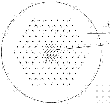
[0014] A flat-top photonic bandgap fiber is composed of two low-refractive-index dielectric pillars 2 with different diameters, wherein the inner low-refractive-index dielectric pillar 2 has a larger diameter, while the outermost low-refractive-index dielectric pillar 2 has a smaller diameter , so as to obtain a better refractive index distribution. By adjusting the diameter of the dielectric column, the equivalent refractive index in different regions of the fiber core can be adjusted, so that the distribution of the refractive index in the fiber core region can be precisely controlled. During fabrication, the low-refractive-index medium columns have the same refractive index, which also reduces the complexity of the fabrication process.

[0015] figure 1 A cross-sectional schematic view of an embodiment of the present invention is provided, the optical fiber comprises a core and a cladding, the core is made of a low-refractive index dielectric column 2 and a matrix material...


PUM

PropertyMeasurementUnit
refractive indexaaaaaaaaaa

Abstract

Disclosed is a flat-top photonic band gap fiber. According to the flat-top photonic band gap fiber, a fiber core is composed of a host material and low-refractive-index dielectric cylinders distributed in an equilaterally triangular grid, a cladding is composed of a host material and high-refractive-index dielectric cylinders distributed in an equilaterally triangular grid, the fiber core is surrounded by the cladding, the refractive indexes of materials meet the inequation n[h]>n[b]>n[1], the high-refractive-index dielectric cylinders form a regular hexagon-shaped high-refractive-index dielectric cylinder layer, the low-refractive-index dielectric cylinders form a regular hexagon-shaped low-refractive-index dielectric cylinder layer, and the diameter of the low-refractive-index dielectric cylinder on the outmost layer and the diameters of other low-refractive-index dielectric cylinders meet the inequation d[m]<d[1]. According to the flat-top photonic band gap fiber, by introducing the low-refractive-index dielectric cylinders, refractive index distribution required by a flat-top beam is formed by means of the low-refractive-index dielectric cylinders in different sizes, and the area of a fundamental mode is increased; band gaps are formed by means of the high-refractive-index dielectric cylinders of the cladding, and the fiber core mode is highly constrained. The flat-top photonic band gap fiber can be applied to the output end of a fiber laser device to achieve large-mode-field flat-top beam output.

Description

technical field [0001] The invention relates to a fiber laser, in particular to a flat-top photonic bandgap fiber. Background technique [0002] Top-hat beams have important applications in the field of laser processing. For example, in laser welding, in order to obtain a better welding effect, it is usually necessary to make the solder joints heated evenly, which requires the optical field distribution of the laser beam to be flat-topped. Good reinforcement. There are many ways to obtain a flat-top laser beam. Although a flat-top beam can be obtained by using an optical system for transformation, the system stability is poor; another method is to use a flat-top optical fiber to shape the incident laser beam into a laser with a flat-top optical field distribution. bundle. The so-called flat-top fiber means that the laser beam output through it has a flat-top mode field structure. As we all know, the optical field of the laser beam output from an ordinary optical fiber on...

Claims


Application Information

Patent Timeline
Patent Type & Authority Patents(China)
IPC IPC(8): G02B6/02
CPCG02B6/02323G02B6/02338
Inventor 王华陈明阳祝远锋李路明杨济海陈磊
Owner STATE GRID CORP OF CHINA
Why Eureka
Try Eureka