A suspended edge coupler for mid-infrared band

An infrared band and coupler technology, applied in the field of couplers, can solve the problems of large waveguide-fiber coupling loss in the mid-infrared band, and achieve the effects of convenient testing, increased coupling area, and increased process tolerance

Active Publication Date: 2021-07-27
SHANGHAI INST OF MICROSYSTEM & INFORMATION TECH CHINESE ACAD OF SCI
View PDF7 Cites 0 Cited by
  • Summary
  • Abstract
  • Description
  • Claims
  • Application Information

AI Technical Summary

Problems solved by technology

[0004] The technical problem to be solved by the present invention is to provide a suspended edge coupler applied in the mid-infrared band, which solves the problem of large waveguide-fiber coupling loss in the mid-infrared band

Method used


Image

  • A suspended edge coupler for mid-infrared band
  • A suspended edge coupler for mid-infrared band

Examples


Embodiment 1

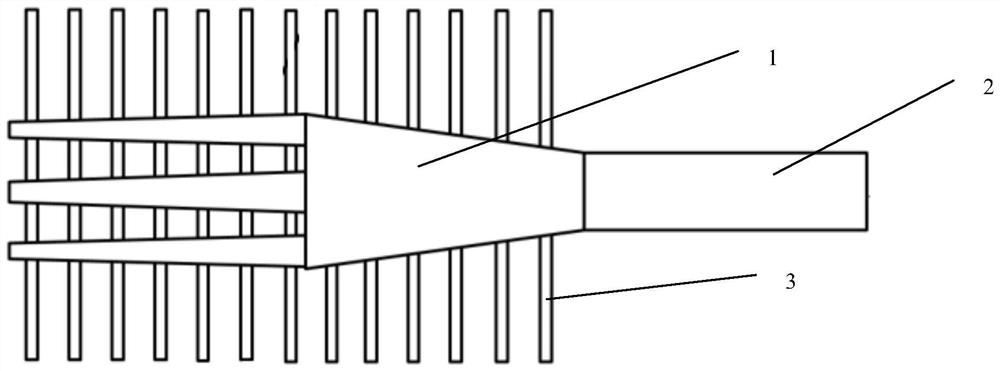
[0016] Depend on figure 1 As shown, this embodiment provides a suspended edge coupler applied in the mid-infrared band, including a three-port inverted cone coupler 1, a suspended ridge waveguide 2 and a cantilever arm support structure 3; the three-port inverted cone The shaped coupler 1 is directly connected to the suspended ridge waveguide 2; the cantilever arm support structure 3 is used to support the three-port inverted tapered coupler 1. The ports in the three-port inverted tapered coupler 1 are used to receive light input in the mid-infrared band. The cantilever arm support structure 3 is composed of a plurality of parallel strip waveguides.

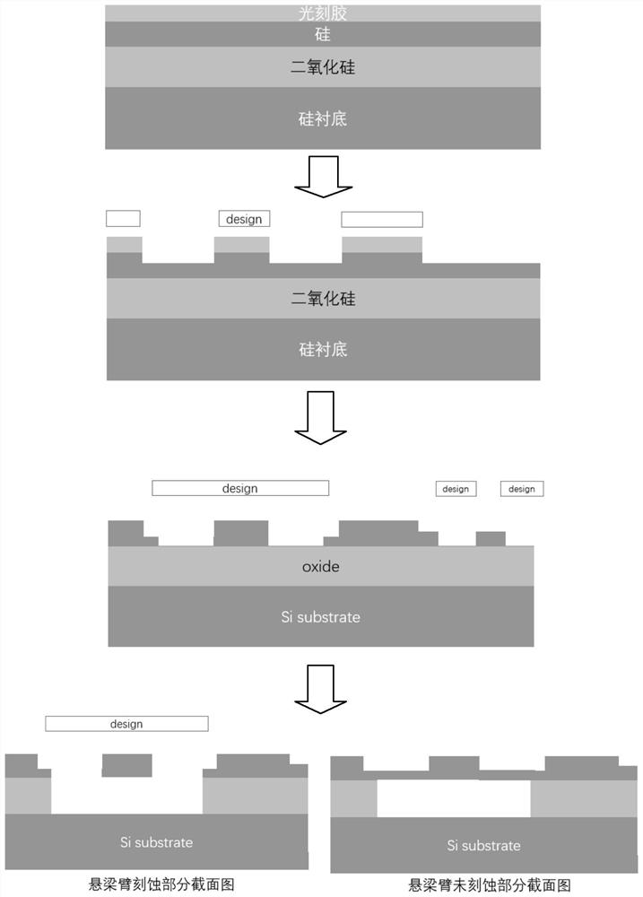
[0017] Depend on figure 2 As shown, this embodiment also provides a method for preparing a suspended edge coupler applied in the mid-infrared band, including the following steps:

[0018] (1) This structure is suitable for SOI materials of silicon photonics devices, in which the thickness of the silicon dioxide layer is gene...


PUM


Abstract

The invention relates to a suspended edge coupler applied in the mid-infrared band, comprising a three-port inverted tapered coupler (1), a suspended ridge waveguide (2) and a cantilever arm support structure (3). The invention increases the coupling efficiency through the unique structural design, increases the process tolerance at the same time, and also brings great convenience to the test, solves the problem of large coupling loss of the mid-infrared band waveguide-optical fiber, and has good application prospect.

Description

technical field [0001] The invention belongs to the field of couplers, in particular to a suspended edge coupler applied in the mid-infrared band. Background technique [0002] SOI material is an important optical waveguide material used in silicon-based photonics. It is compatible with mature CMOS processes, has low production costs and high process stability. The mid-infrared band (2μm-20μm) is an important band range in the spectrum, and the absorption peaks of many gases are concentrated in this band, so it has important applications in sensing. The absorption loss of silicon material is very low at 3-8um, but the absorption loss of the substrate silicon dioxide is higher after the wavelength >3.5μm. Therefore, if the transmission loss of the silicon-based waveguide prepared by traditional SOI material is large, Also conventional couplers face the same problem. For the problem of large waveguide transmission loss, the method of hollowing out the silicon dioxide subs...

Claims


Application Information

Patent Timeline
Patent Type & Authority Patents(China)
IPC IPC(8): G02B6/122
CPCG02B6/122G02B6/1228G02B2006/12147
Inventor 王书晓王庆蔡艳余明斌王曦
Owner SHANGHAI INST OF MICROSYSTEM & INFORMATION TECH CHINESE ACAD OF SCI
Why Eureka
Try Eureka