A laser beam pulse timing synthesis device based on diffraction grating

A technology of laser beam and pulse timing, which is applied in the laser field, can solve the problems of increased complexity and synchronization control accuracy, and achieve the effect of increasing the number of synthesis channels, reducing the complexity and difficulty of synchronization control, and avoiding the decline of synthesis efficiency

Active Publication Date: 2017-06-16
TECHNICAL INST OF PHYSICS & CHEMISTRY - CHINESE ACAD OF SCI
View PDF6 Cites 0 Cited by
  • Summary
  • Abstract
  • Description
  • Claims
  • Application Information

AI Technical Summary

Problems solved by technology

Each synthesis module in the optical path of this scheme can only add one synthesis sub-laser to synthesize N sub-lasers. The system needs N-1 synthesis motors and rotating mirrors. Therefore, as the number of synthesis sub-lasers increases, the complexity of the system will increase. And the requirements for synchronous control accuracy also increase
[0006] To sum up, each laser synthesis technology has its unique advantages, but each laser synthesis technology is limited in different degrees and aspects in achieving high power and high beam quality laser synthesis

Method used


Image

  • A laser beam pulse timing synthesis device based on diffraction grating
  • A laser beam pulse timing synthesis device based on diffraction grating
  • A laser beam pulse timing synthesis device based on diffraction grating

Examples


Embodiment 1

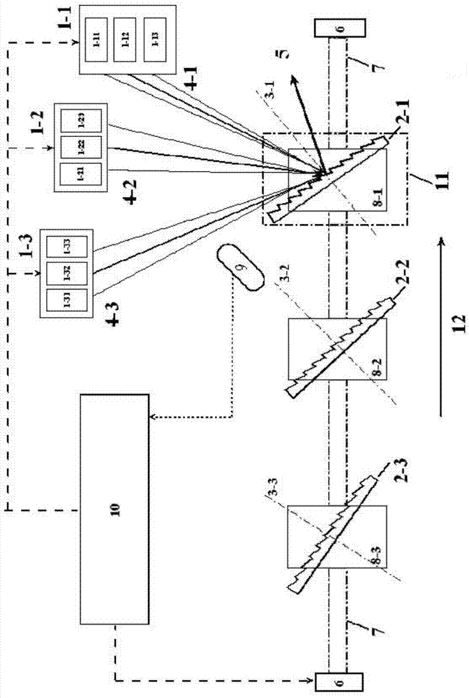
[0041] See image 3 , which is a schematic structural diagram of a laser beam pulse timing synthesis device based on a cyclically moving reflective grating.

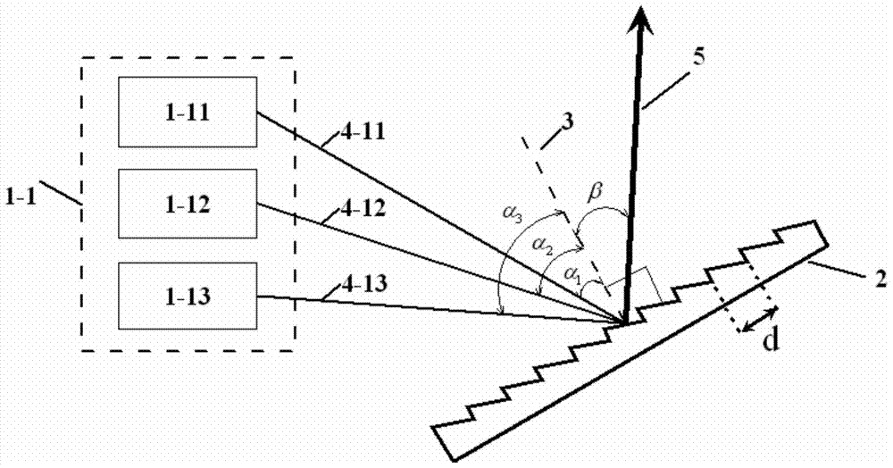
[0042] In the first embodiment, each pulse laser group is matched with its own grating, the position of the pulse laser group is fixed, and all the gratings are installed on the transmission device; the transmission device is connected with the synchronous control device, so that all The synchronous control device obtains the position information of the grating in the transmission device; the transmission device includes a motor and a main transmission member; the motor drives the main transmission member to move; the grating is installed on the main transmission member, and Driven by the main transmission member, it performs periodic movement in the same direction, so that the grating sequentially reaches the corresponding working position of the pulse laser group.

[0043] In the first embodiment, the pulsed laser uni...

Embodiment 2

[0056] See Figure 4 , which is a schematic structural diagram of a laser beam pulse timing synthesis device based on a vertically reciprocating transmission grating.

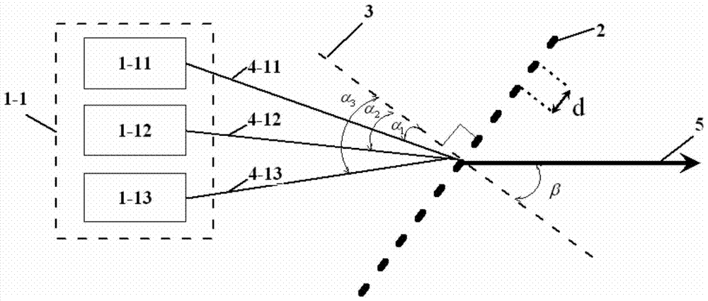
[0057] In the second embodiment, each pulse laser group is matched with its own grating, all the pulse laser groups are located on the same plane and their positions are fixed, and the sub-lasers of each pulse laser group are respectively located on both sides of the main optical path; The grating and the pulse laser group are distributed at intervals in the direction of the main optical path, and all the gratings are located in front of the matched pulse laser group and installed on their corresponding grating driving devices; the grating driving device and the The synchronous control device is connected to drive the grating to move periodically under the control of the synchronous control device. It should be noted here that all the gratings located in front of the matched pulse laser group refer to being lo...

Embodiment 3

[0067] See Figure 5 , which is a structural schematic diagram of a laser beam pulse timing synthesis device based on a fan-shaped or circular-moving transmission grating.

[0068] Different from the first embodiment, the main transmission part in the third embodiment is the rotating shaft 14 . The pulsed laser groups are sequentially distributed on one side of the rotating shaft 14 along the axial direction of the rotating shaft, and all the pulsed laser groups are located on the same plane; On both sides; the grating is installed in the laser transmission direction of the matched pulse laser group; and the grating and the pulse laser group are distributed axially at intervals; the grating is along the circumferential direction of the rotating shaft are distributed sequentially so that when the rotating shaft rotates, the grating passes through the planes where all the pulsed laser groups are located, and intersects with the main optical path 5; and, the fixed position of th...


PUM


Abstract

The invention relates to the field of the laser technology, and provides a laser beam pulse time sequence synthesizer based on diffraction gratings. The laser beam pulse time sequence synthesizer based on the diffraction gratings comprises a plurality of pulse laser sets and the gratings corresponding to the pulse laser sets, wherein when one grating moves to the work position of the corresponding pulse laser set, a synchronous control device sends an instruction to the corresponding pulse laser set and triggers the pulse laser set to output pulse laser, so that the pulse laser enters a preset main optical path under the diffraction action of the grating, and moreover, the grating does not prevent pulse laser output by other pulse laser sets from entering the main optical path when not in the work positions of the pulse. The laser beam pulse time sequence synthesizer based on the diffraction gratings integrates the spectrum synthesis technology and the mechanical time sequence synthesis technology, increases the number of synthesis paths of pulse laser and keeps good light beam quality on the premise of not reducing sub-laser wavelength intervals or the number of the diffraction gratings.

Description

technical field [0001] The invention relates to the field of laser technology, in particular to a diffraction grating-based laser beam pulse timing synthesis device. Background technique [0002] Generally speaking, as the output power of a single laser increases, its beam quality will decrease nonlinearly. Therefore, combining multiple laser beams into one beam is an important method to obtain high-power and high-beam quality lasers. The current laser beam synthesis technology mainly includes: direct synthesis technology, coherent synthesis technology, polarization synthesis technology, spectral synthesis technology, pulse timing synthesis technology, etc. [0003] The direct synthesis technology is to superimpose multiple sub-lasers side by side in sequence, or realize the beam synthesis of multiple sub-lasers by means of beam shaping and transformation. It has the advantages of simple principle and high stability. However, the beam quality of the synthesized laser will ...

Claims


Application Information

Patent Timeline
Patent Type & Authority Patents(China)
IPC IPC(8): H01S3/23H01S5/40
Inventor 高宏伟韩琳彭钦军薄勇徐一汀徐健许家林许祖彦
Owner TECHNICAL INST OF PHYSICS & CHEMISTRY - CHINESE ACAD OF SCI
Why Eureka
Try Eureka