Novel power tool holder for machine tool machining

A technology of driven tool holders and machine tools, which is applied in metal processing equipment, metal processing machine parts, manufacturing tools, etc., can solve the problems of reducing work efficiency and the effective utilization rate of tools, and achieve simple structure, effective work efficiency and reasonable design Effect

Active Publication Date: 2015-02-04
统弘自动化科技(苏州)有限公司
View PDF8 Cites 3 Cited by
  • Summary
  • Abstract
  • Description
  • Claims
  • Application Information

AI Technical Summary

Problems solved by technology

However, the existing machine tool holders can only perform cutting operations in a fixed direction after the tool is installed, and it is difficult for the tool body to change the cutting direction, thus limiting the development of the processing technology, and when cutting at different angles, it is usually necessary to replace the tool or readjust The position of the tool seat reduces the work efficiency and the effective utilization of the tool

Method used


Image

  • Novel power tool holder for machine tool machining
  • Novel power tool holder for machine tool machining

Examples


Embodiment 1

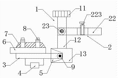
[0017] A new type of power tool holder for machine tool processing, including: a tool holder main body 1, a clamping mechanism 2, a tool support seat 3, an angle adjuster 4 and a locking screw 9;

[0018] The tool seat main body 1 is composed of a nut 11, a connecting rod 12 and a tool seat head 13, wherein the nut 11 and the tool seat head 13 are respectively fixedly installed at both ends of the connecting rod 12;

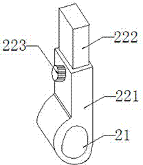
[0019] The clamping mechanism 2 is composed of a clamping sleeve 21 and a clamping handle 22, and the clamping sleeve 21 is movably sleeved on the connecting rod 12 through a fastening screw 23, so that the clamping mechanism 2 is positioned on the knife. Fixing and moving up and down on the seat main body 1, that is, by loosening the fastening screw 23, the clamping mechanism 2 moves up and down along the connecting rod 12 to change the cutting position of the cutter body in the vertical direction. When the fastening screw is tightened After 23, the holding mech...

Embodiment 2

[0023] The difference from Embodiment 1 is that an isosceles trapezoidal groove 5 is provided on the other side of the tool seat head 13 adjacent to the connecting rod 12 .

Embodiment 3

[0025] The difference from Embodiment 1 is that an isosceles trapezoidal groove 5 is provided on the side of the tool seat head 13 opposite to the connecting rod 12 .

[0026] The invention discloses a new type of power tool seat for machine tool processing, which has a simple structure and a reasonable design. Through the design of the position and structure of the clamping mechanism, the cutting position of the tool body in the vertical direction and the cutting depth in the horizontal direction are changed; The design of the structure and connection method between the tool support seat and the tool seat main body changes the cutting angle of the tool body; the invention can quickly and conveniently adjust the cutting of the tool body without changing the tool or readjusting the position of the tool seat. Position, cutting depth and cutting angle, effectively improving work efficiency and tool utilization.


PUM


Abstract

The invention discloses a novel power tool holder for machine tool machining. The novel power tool holder comprises a tool holder main body, a clamping mechanism, a cutting tool bearing seat, an angle adjuster and a locking screw, wherein the tool holder main body consists of a nut, a connecting rod and a tool holder head, and the nut and the tool holder head are fixed at the two ends of the connecting rod; the clamping mechanism consists of a clamping sleeve and a clamping handle, and the clamping sleeve is movably arranged on the connecting rod through a fastening screw in a sleeving mode; a trapezoidal groove is formed in one side of the tool holder head, one end of the cutting tool bearing seat is inserted in the trapezoidal groove, a cutter body and a cutter body pressing plate are fixedly mounted above the cutting tool bearing seat in sequence, the angle adjuster is arranged below the cutting tool bearing seat, the angle adjuster is used for adjusting and controlling the cutting tool bearing seat to perform a rotary motion along the axis of the cutting tool bearing seat so as to change the cutting angle of the cutter body. The novel power tool holder is simple in structure and reasonable in design; under the precondition that a cutting tool is not changed or the position of the tool holder is not readjusted, the cutting position, cutting depth and cutting angle of the cutter body can be quickly and conveniently adjusted, and the work efficiency and the utilization rate of the cutting tool are effectively improved.

Description

technical field [0001] The invention relates to the technical field of machine tool parts, in particular to a novel dynamic tool holder for machine tool processing. Background technique [0002] The CNC machine tool is a powerful high-precision machining machine tool. It uses a computer program to control the tool, and according to the predetermined program, the workpiece is fed and retracted, and the cutting work is automatically completed. However, the existing machine tool holders can only perform cutting operations in a fixed direction after the tool is installed, and it is difficult for the tool body to change the cutting direction, thus limiting the development of the processing technology, and when cutting at different angles, it is usually necessary to replace the tool or readjust The position of the tool seat reduces the work efficiency and the effective utilization rate of the tool. Contents of the invention [0003] The main technical problem to be solved by th...

Claims


Application Information

Patent Timeline
Patent Type & Authority Applications(China)
IPC IPC(8): B23Q3/00
CPCB23Q3/00
Inventor 付冲
Owner 统弘自动化科技(苏州)有限公司
Why Eureka
Try Eureka