
Manufacturing equipment for reinforced metal spiral bellows

A technology for spiral corrugated pipes and manufacturing equipment, which is applied in the field of manufacturing equipment for the production of reinforced metal spiral corrugated pipes. It can solve the problems of spending a lot of time adjusting the angle, affecting the accuracy of backup rollers, and taking a long time for replacement, so as to improve product quality. , Improve the smoothness of the inner wall, and have good equipment versatility

Active Publication Date: 2016-10-05
昆山通塑挤出机械制造有限公司
View PDF6 Cites 0 Cited by
  • Summary
  • Abstract
  • Description
  • Claims
  • Application Information

AI Technical Summary

Problems solved by technology

[0002] At present, the plastic strip and the corresponding metal reinforcement are spirally wound layer by layer to form a metal spiral corrugated pipe. In order to produce the reinforced metal spiral corrugated pipe with the above structure, a reinforced metal spiral corrugated pipe is introduced in Chinese patent 200820064740.0. The manufacturing device of the spiral corrugated pipe, in which a fixed main support roller and a movable main support roller are used in the threaded pipe wall forming unit to form an annular support surface, but in this way, once the movable main support is removed After being stuck, it must be shut down for maintenance before continuing to work, and the minimum diameter of the reinforced metal spiral corrugated pipe manufactured with a fixed-movable main support roll configuration is limited by the fixed main support roll, which is a part that needs to be improved
Furthermore, in patent 200820064740.0, if it is necessary to replace the back-up roll in the threaded pipe wall forming unit, the entire replacement process of the workers is bent in a narrow space, which affects the installation accuracy of the back-up roll. It takes a long time and it takes a lot of time to adjust the angle. These are problems that need to be solved

Method used


Image

  • Manufacturing equipment for reinforced metal spiral bellows
  • Manufacturing equipment for reinforced metal spiral bellows
  • Manufacturing equipment for reinforced metal spiral bellows

Examples


Embodiment

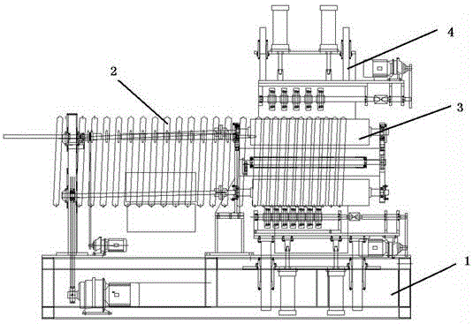
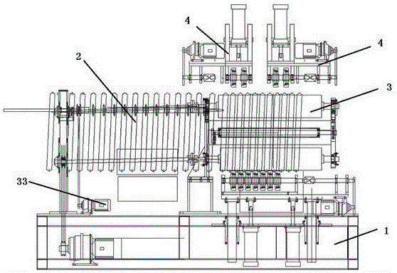
[0032] Such as figure 1 , 2 The manufacturing equipment for a reinforced metal spiral corrugated pipe shown is, on the base 1, along the pipe advancing direction, there are successively provided: a metal reinforcing rib forming push unit 2, a threaded pipe wall forming unit 3, and a rolling unit 4; Before the metal reinforcing rib is sent into the threaded pipe wall forming unit 3, a device for heating the metal reinforcing rib is also provided. The metal reinforcing rib forming and pushing unit 2 includes: a metal strip bending forming mechanism and a forming reinforcing rib pushing mechanism.

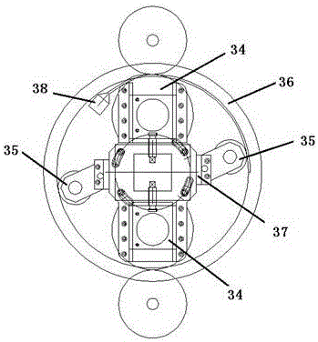
[0033] The metal reinforcing rib forming unit bends the metal strip into the required shape through the metal strip bending forming mechanism, and then sends the metal reinforcing rib into the threaded pipe wall forming unit 3 through the pushing mechanism of the formed reinforcing rib; the threaded pipe wall forming unit 3 The main support roller driving mechanism 33 drives the mai...


PUM


Abstract

The invention discloses a manufacturing device of an enhanced metal spiral corrugated pipe. The manufacturing device comprises a thread pipe wall molding unit; at least two main support rollers are arranged at the internally tangent part of a ring-shaped support surface; the main support rollers are movably arranged on a support frame by an adjusting mechanism, so that the ring-shaped support surface can be adjusted along the radial direction; the axial directions of the main support rollers are located by an axial support locating rod; the main support rollers are driven to rotate by a main support roller driving mechanism. According to the manufacturing device, all the main support rollers are movably connected, so that the production demands of various corrugated pipes with different diameters can be met to the utmost extent; devices with different models do not needed to be added within a certain range, so that the manufacturing device is good in universality.

Description

technical field [0001] The invention relates to the field of mechanical equipment manufacturing, in particular to a manufacturing equipment for producing reinforced metal spiral corrugated pipes. Background technique [0002] At present, the plastic strip and the corresponding metal reinforcement are spirally wound layer by layer to form a metal spiral corrugated pipe. In order to produce the reinforced metal spiral corrugated pipe with the above structure, a reinforced metal spiral corrugated pipe is introduced in Chinese patent 200820064740.0. The manufacturing device of the spiral corrugated pipe, in which a fixed main support roller and a movable main support roller are used in the threaded pipe wall forming unit to form an annular support surface, but in this way, once the movable main support is removed After being stuck, it must be shut down for maintenance before continuing to work, and the minimum diameter of the reinforced metal spiral corrugated pipe manufactured ...

Claims


Application Information

Patent Timeline
Patent Type & Authority Patents(China)
IPC IPC(8): B29C69/02B29C47/02B29C47/08B29C47/92B29C43/58B29D23/00B29D16/00B29C48/92
Inventor 张汝忠
Owner 昆山通塑挤出机械制造有限公司
Learn More