
Multi-point jet stirring hybrid anaerobic digester system

An anaerobic digestion tank, stirring and mixing technology, applied in anaerobic digestion treatment, multi-stage water treatment, chemical instruments and methods, etc., can solve problems such as easy blockage of jet holes, influence of treatment effect, failure of treatment system, etc., to achieve guaranteed The effect of normal operation, improvement of processing effect, and improvement of processing efficiency

Active Publication Date: 2015-02-04
HUBEI WEINENG ENVIRONMENTAL PROTECTION ENG
View PDF4 Cites 2 Cited by
  • Summary
  • Abstract
  • Description
  • Claims
  • Application Information

AI Technical Summary

Problems solved by technology

[0004] The distribution of the above three stirring methods has the following defects: (1) mechanical stirring has the disadvantage of insufficient mixing of digestive juice and anaerobic sludge; (2) biogas stirring is a method clearly stipulated by the Ministry of Environmental Protection, but it must be explosion-proof compressor to avoid the potential risk of explosion, and it needs to be used in conjunction with a submersible mixer, which has no advantages in terms of energy saving; (3) The stirring of ordinary circulating digestive juice is formed by pressurized injection of a single throat. The mixing volume of the mixing method is limited, and the amount of sewage treated by this method is extremely limited
However, with the current multi-point jet agitation, after the digestive fluid is injected and mixed with the sludge in the sedimentation area, it is easy to block the jet holes, resulting in uneven water distribution, affecting the treatment effect, and even causing the treatment system to fail.

Method used


Image

  • Multi-point jet stirring hybrid anaerobic digester system
  • Multi-point jet stirring hybrid anaerobic digester system
  • Multi-point jet stirring hybrid anaerobic digester system

Examples


Embodiment Construction

[0023] In order to make the object, technical solution and advantages of the present invention clearer, the present invention will be further described in detail below in conjunction with the accompanying drawings and embodiments. It should be understood that the specific embodiments described here are only used to explain the present invention, not to limit the present invention.

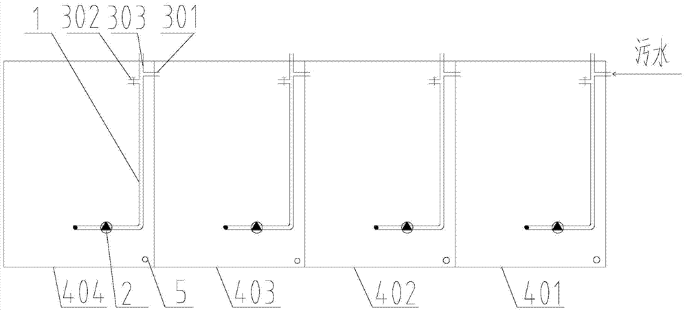
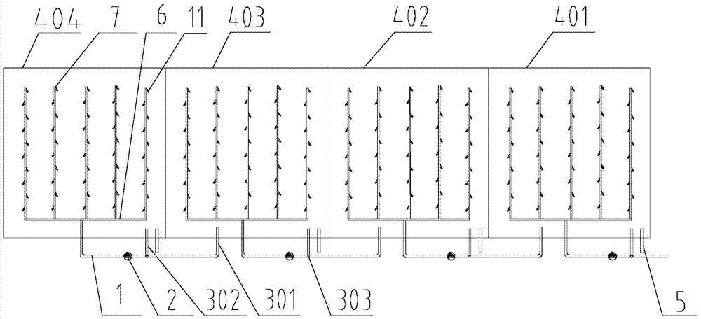
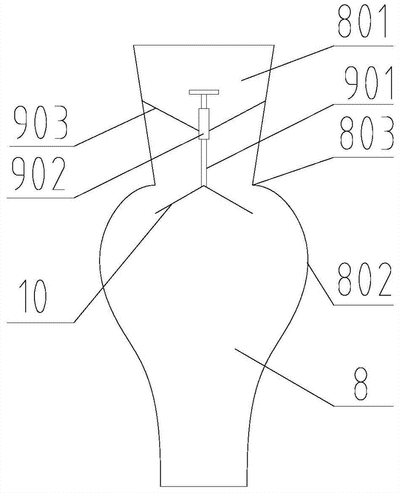
[0024] In a preferred embodiment of the present invention, as Figure 1~Figure 3 As shown, a multi-point jet stirring mixed anaerobic digester system, the system includes: at least two stages of anaerobic digesters, water inlet devices arranged outside each stage of anaerobic digesters, arranged in each stage of anaerobic digesters The water distribution device in the sludge layer of the pool and the sludge discharge pipe 5 arranged at the bottom of each level of anaerobic digestion tank; wherein,

[0025] The water inlet device includes a circulating water inlet pipe 1 and a circulating pump 2. T...


PUM


Abstract

The invention discloses a multi-point jet stirring hybrid anaerobic digester system, comprising at least two stages of anaerobic digesters, a water feeding device, a water distribution device and a sludge discharge pipe, wherein the water feeding device comprises a circulating water inlet pipe and a circulating pump, the top of the circulating water inlet pipe is at least connected with two branch pipes, the first branch pipe outside the top anaerobic digester is communicated with sewage, the first branch pipe outside next stage of anaerobic digester is communicated with the supernate layer of the last stage of anaerobic digester, and the second branch pipes are communicated with the supernate layers of the corresponding anaerobic digesters; and the water distribution device comprises a water distribution main pipe, a water distribution branch pipe and an anti-blocking nozzle. By adopting the system, sludge can be prevented from entering the nozzle to cause blocking, uniform water distribution is ensured, the treatment effect is improved, normal operation of the treatment system is ensured, digestive liquid can sufficiently contact and be mixed with sludge, and the treatment efficiency of the anaerobic digesters is greatly improved.

Description

technical field [0001] The invention belongs to the technical field of anaerobic treatment of wastewater, and in particular relates to a multi-point jet agitation mixing type anaerobic digestion tank system. Background technique [0002] Anaerobic biological wastewater treatment technology is an important technology in environmental engineering and energy engineering, and it is one of the powerful treatment methods for organic wastewater. In the past, it was mostly used for the treatment of sludge, organic waste and some high-concentration organic wastewater in urban sewage treatment plants. The structure type mainly uses ordinary digesters. [0003] Ordinary digesters, also known as traditional or conventional digesters, have a history of more than 100 years and can directly process feed liquids with high suspended solids content or large particles. The waste water enters the tank regularly or continuously, the digested sludge and waste water are discharged from the bottom...

Claims


Application Information

Patent Timeline
Patent Type & Authority Applications(China)
IPC IPC(8): C02F3/28
CPCC02F3/286C02F2301/08
Inventor 罗子清
Owner HUBEI WEINENG ENVIRONMENTAL PROTECTION ENG
Learn More