Bulb through-flow turbine

The technology of one-type water turbine and light bulb through-flow is applied in the direction of reaction engine, mechanical equipment, hydroelectric power generation, etc., which can solve the problems of increasing hydraulic loss, large space to adjust the pipeline, reducing the recoverable water head, etc., to achieve hydraulic loss. Small, simple and convenient to use, avoiding the effect of transformation requirements

Inactive Publication Date: 2015-02-04
上海福思特流体机械有限公司
View PDF17 Cites 9 Cited by
  • Summary
  • Abstract
  • Description
  • Claims
  • Application Information

AI Technical Summary

Problems solved by technology

However, in the field of general industrial applications, due to the limitation of pipeline direction, installation location and process flow, there is no suitable location to install the shaft extension tubular turbine with the inlet and outlet at an angle of 90°, so it is necessary to configure multiple bends. The head is used to adjust the direction of the pipeline, while the elbow will increase the hydraulic loss and reduce the recoverable water head
And if the diameter of the pipeline is larger, a larger space is needed to adjust the direction of the pipeline, which will also be limited by site conditions

Method used


Image

  • Bulb through-flow turbine
  • Bulb through-flow turbine

Examples


Embodiment Construction

[0041] The following will clearly and completely describe the technical solutions in the embodiments of the present invention with reference to the accompanying drawings in the embodiments of the present invention. Obviously, the described embodiments are only some, not all, embodiments of the present invention. Based on the embodiments of the present invention, all other embodiments obtained by persons of ordinary skill in the art without creative efforts fall within the protection scope of the present invention.

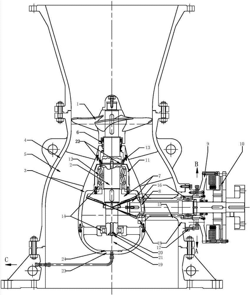
[0042] figure 1 It is a structural schematic diagram of the first embodiment of the bulb tubular water turbine according to the present invention.

[0043] Such as figure 1 As shown, the present invention mainly provides a bulb tubular turbine. In the first embodiment of the present invention, the bulb tubular turbine includes a housing 4, a bulb body 3, a runner 1 and a main shaft 2, a bulb body 3, The runner 1 and the main shaft 2 are arranged inside the housin...


PUM


Abstract

The invention belongs to the technical field of hydroelectric power generating equipment of a fluid flow machine and mainly provides a bulb through-flow turbine. The bulb through-flow turbine comprises a shell, a bulb body, a runner and a spindle, wherein the bulb body, the runner and the spindle are arranged in the shell; one end of the spindle extends into the bulb body, and the other end of the spindle is located at the outer part of the bulb body and is connected with the runner; the spindle is provided with a first bevel gear; the first bevel gear is located in the bulb body. The bulb through-flow turbine is characterized by comprising a countershaft; the countershaft is provided with a second bevel gear; the first bevel gear and the second bevel gear are meshed to form a bevel gear pair; transmission is realized between the countershaft and the spindle through the bevel gear pair; the countershaft is provided with an electromagnetic power-off brake; the electromagnetic power-off brake is structurally and electrically connected with the bulb through-flow turbine.

Description

technical field [0001] The invention belongs to the technical field of hydraulic power generation equipment of fluid machinery, and more specifically, the invention relates to a bulb tubular water turbine capable of generating electricity efficiently. Background technique [0002] The bulb tubular turbine is one of the important types of tubular turbines. Its applied water head is generally below 25m. It is mainly used in tidal power stations and low-head power stations on rivers. Generally, the generator and the turbine are directly connected. The generator is installed in inside the bulb. Because of its structure, it basically runs through the axial direction from the water inlet to the water outlet, without turning, the size of the flow channel is large and short, the hydraulic loss of the flow channel is small, the unit has high efficiency, simple structure, and convenient construction. [0003] In some industrial residual pressure recovery and utilization fields, the w...

Claims


Application Information

Patent Timeline
Patent Type & Authority Applications(China)
IPC IPC(8): F03B3/04F03B11/00
CPCF03B3/04F03B11/00F03B15/00F05B2260/903F05B2260/98Y02E10/20
Inventor 张浩寿满光陈德泉童弘林永池鲁恒杨见文
Owner 上海福思特流体机械有限公司
Why Eureka
Try Eureka