Screw rotor cooling device of screw vacuum pump

A screw vacuum pump and rotor cooling technology, which is applied to the components, pumps, and pump components of the pumping device for elastic fluid, can solve the increase of noise and vibration of the screw vacuum pump, affect the dynamic balance performance of the screw rotor, and it is difficult to accurately control the cooling. Cavity size and other issues, to achieve the effect of improving yield, improving cooling effect, and easy monitoring

Active Publication Date: 2015-02-04
MADEBAO VACUUM EQUIP GRP
View PDF6 Cites 20 Cited by
  • Summary
  • Abstract
  • Description
  • Claims
  • Application Information

AI Technical Summary

Problems solved by technology

Since the existing screw is usually processed by casting, it can be known from the text and drawings of the two patent documents that the hollow structure of the helical teeth is obtained during the casting process. The problem with such a structure is that it is difficult to accurately control the size of the cooling cavity during casting. , which seriously affects the dynamic balance performance of the screw rotor, the castings are prone to various defects, resulting in low yield, and the noise and vibration of the screw vacuum pump will also increase
Moreover, the screw shaft is cooled separately through the cooling oil pump, the cooling cavity is not well utilized, and the cooling effect is not good

Method used


Image

  • Screw rotor cooling device of screw vacuum pump
  • Screw rotor cooling device of screw vacuum pump

Examples


Embodiment Construction

[0020] The following are specific embodiments of the present invention and in conjunction with the accompanying drawings, the technical solutions of the present invention are further described, but the present invention is not limited to these embodiments.

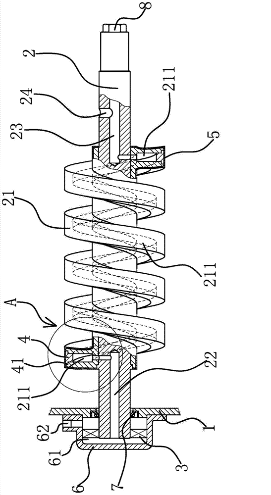
[0021] The screw vacuum pump includes a pump body 1 and a screw rotor 2, the screw rotor 2 is installed in the pump body 1, and the screw rotor 2 is made of metal material. The screw rotor cooling device of the screw vacuum pump includes a hydraulic pump 3 , a coolant tank and a coolant channel 211 .

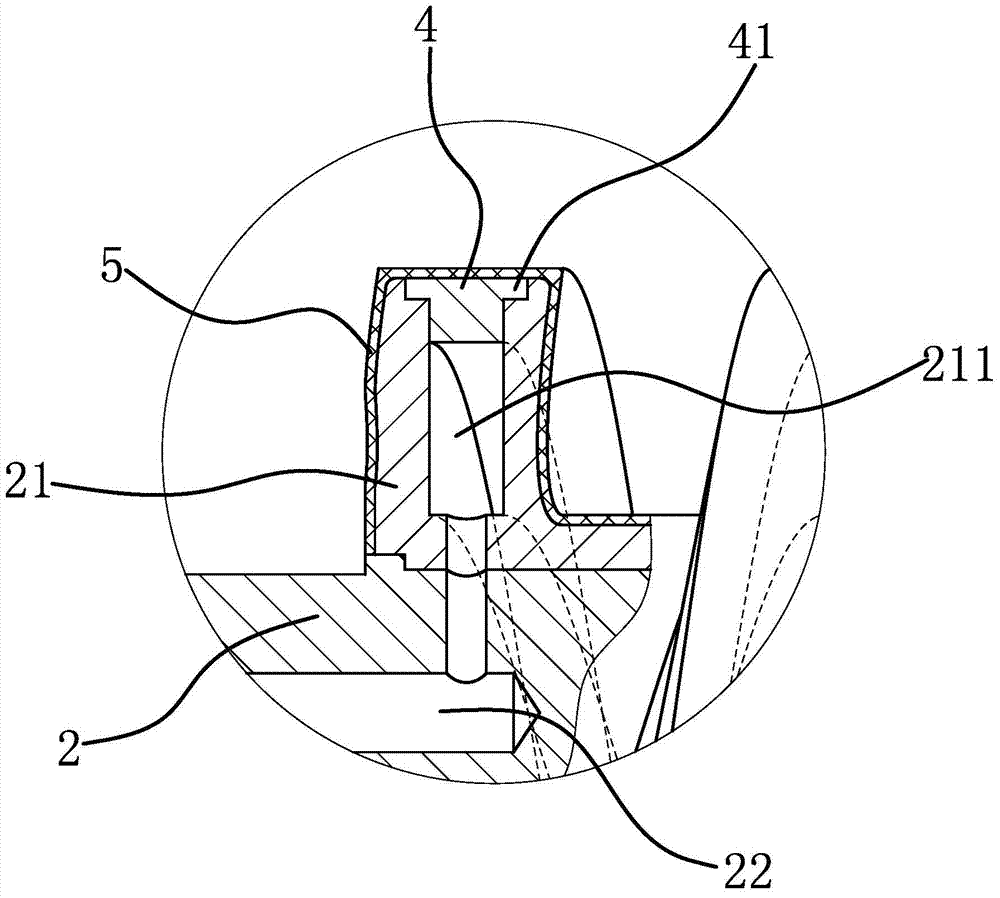
[0022] Specifically, as figure 1 As shown, the screw rotor 2 has helical teeth 21 , and the cooling liquid channel 211 is opened on the helical teeth 21 of the screw rotor 2 along the helical direction of the helical teeth 21 . The upper surface of the cooling liquid passage 211 has an opening open to the outside world, and an insert 4 matching the shape of the opening is fixed at the opening of the cooling passage. In thi...


PUM


Abstract

The invention provides a screw rotor cooling device of a screw vacuum pump, belonging to the technical field of pumps and solving the problems that an existing screw rotor cooling device of the screw vacuum pump is poor in cooling effect and inconvenient to machine. The screw rotor cooling device comprises a hydraulic pump and a cooling liquid tank; a helical tooth is arranged on a screw rotor, a cooling liquid channel is formed in the helical tooth along the helical direction, an opening opened relative to the outside is formed in the upper surface of the cooling liquid channel, and an insert matched with the shape of the opening is fixed at the opening of the cooling liquid channel; the helical tooth is externally coated by an engineering plastic attaching layer, and the engineering plastic attaching layer covers the joint of the insert and the opening; a liquid inlet end of the cooling liquid channel is communicated with the cooling liquid tank through the hydraulic pump, and a liquid outlet end of the cooling liquid channel is communicated with the cooling liquid tank. According to the screw rotor cooling device of the screw vacuum pump, the cooling liquid channel is formed in the helical tooth of the screw rotor, so that the cooling effect of the screw rotor is relatively good.

Description

technical field [0001] The invention belongs to the technical field of pumps, and relates to a screw vacuum pump, in particular to a screw rotor cooling device of the screw vacuum pump. Background technique [0002] The screw vacuum pump is a suction device that uses a pair of screw rotors to perform synchronous high-speed reverse rotation in the pump casing to generate suction and exhaust. The two screw rotors of the screw vacuum pump need to be finely balanced and corrected, and are supported by bearings and installed in the pump casing. There is a certain gap between the two screw rotors, so when the pump is working, there is no friction between them and the operation is stable. The noise is low, and the working chamber does not need lubricating oil. [0003] The cooling method of the existing screw vacuum pump is to directly cool the pump casing, that is, there is a cooling water channel on the pump casing, and the cooling water is passed to the outside of the pump casi...

Claims


Application Information

Patent Timeline
Patent Type & Authority Applications(China)
IPC IPC(8): F04C29/04F04C18/107
CPCF04C18/107F04C29/042F04C2240/20
Inventor 王于祥张泽武
Owner MADEBAO VACUUM EQUIP GRP
Why Eureka
Try Eureka