Multi-effect double-spiral folded plate heat exchanger
A heat exchanger and double helix technology, applied in the field of multi-effect double helix folded plate heat exchangers, can solve the problems affecting the working efficiency of the heat exchanger, the material cannot achieve cooling or heating effect, etc., and achieve stable and uniform discharge effect, The effect of sufficient contact and high heat transfer efficiency
- Summary
- Abstract
- Description
- Claims
- Application Information
AI Technical Summary
Problems solved by technology
Method used
Image

Examples
Embodiment 1
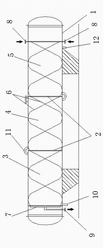
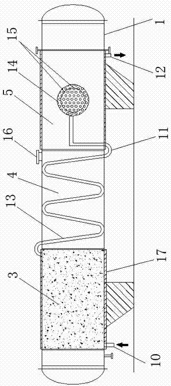
[0017] Example 1: Such as figure 1 and 2 A multi-effect double-helical folded plate heat exchanger is shown, the heat exchanger is a cylindrical shell 1, and the shell 1 is provided with four partitions 2 to separate the shell 1 into three Two heat exchange areas: a sealed heat exchange area 3, a convection heat exchange area 4 and a spray heat exchange area 5. The housing 1 is provided with a material transfer system and a heat exchange system. The material transfer system It consists of two helical pipelines 6 symmetrically installed in the housing 1, the inlet 8 of the helical pipeline 6 is set in the spray heat exchange area 5, and the outlet 9 is set in the sealed heat exchange area 3. The heat exchange system is composed of medium transmission pipelines, the liquid inlet 10 of the medium transmission pipeline is set in the sealed heat exchange area 3 , and the liquid outlet 12 is set in the spray heat exchange area 5 .
Embodiment 2
[0018] Example 2: Such as figure 1 and 2 As shown, the side of the sealed heat exchange area 3 of the present invention is provided with a header 7, and the two spiral pipelines 6 are connected to the outlet 9 through the header 7; Concentrating the materials in the two spiral pipelines 6 to the discharge port 9 for discharge ensures the stable and uniform discharge effect of the heat exchanger and prevents the different heat transfer effects caused by the two spiral pipelines 6 at different positions. This leads to different discharge temperatures.
Embodiment 3
[0019] Example 3: Such as figure 1 and 2 As shown, the spiral pipeline 6 of the present invention is coiled on the inner wall of the housing 1; through the spiral pipeline 6 coiled on the inner wall of the housing 1, the maximum transmission of the spiral pipeline 6 in the housing 1 is ensured At the same time, there is no material transmission pipeline in other positions in the shell 1, which ensures sufficient heat transfer space for the cooling or heating medium in the shell 1.
PUM
 Abstract
Description
Claims
Application Information