
Fiber displacement sensor, fiber displacement detection device and fiber for sensor

A technology of displacement sensor and displacement detection, which is applied in the direction of measuring devices, optical devices, instruments, etc., can solve the problems of high cost, limitation, and complex system, and achieve the effects of low cost, reduced optical fiber cost, and simple system

Inactive Publication Date: 2015-02-04
STATE GRID CORP OF CHINA +2
View PDF10 Cites 8 Cited by
  • Summary
  • Abstract
  • Description
  • Claims
  • Application Information

AI Technical Summary

Problems solved by technology

However, due to the use of fiber gratings in existing displacement sensors, the processing of wavelengths is involved, the system is complex, and the cost is high, which is greatly limited in practical applications.

Method used


Image

  • Fiber displacement sensor, fiber displacement detection device and fiber for sensor
  • Fiber displacement sensor, fiber displacement detection device and fiber for sensor

Examples


Embodiment Construction

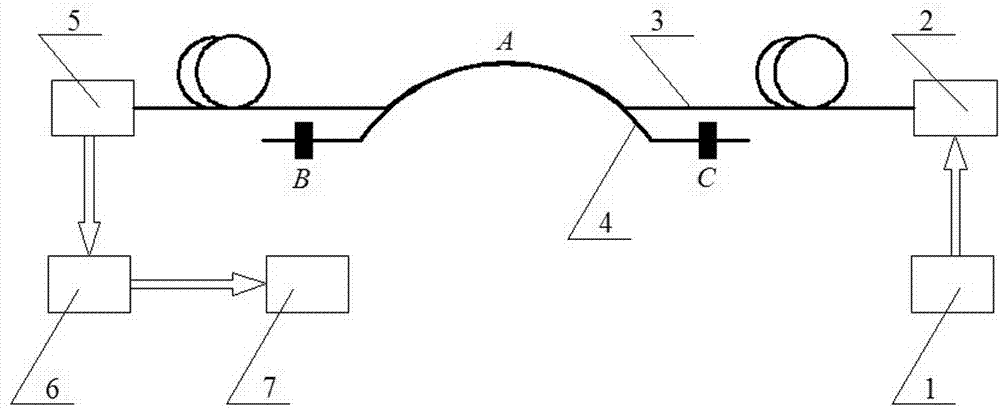
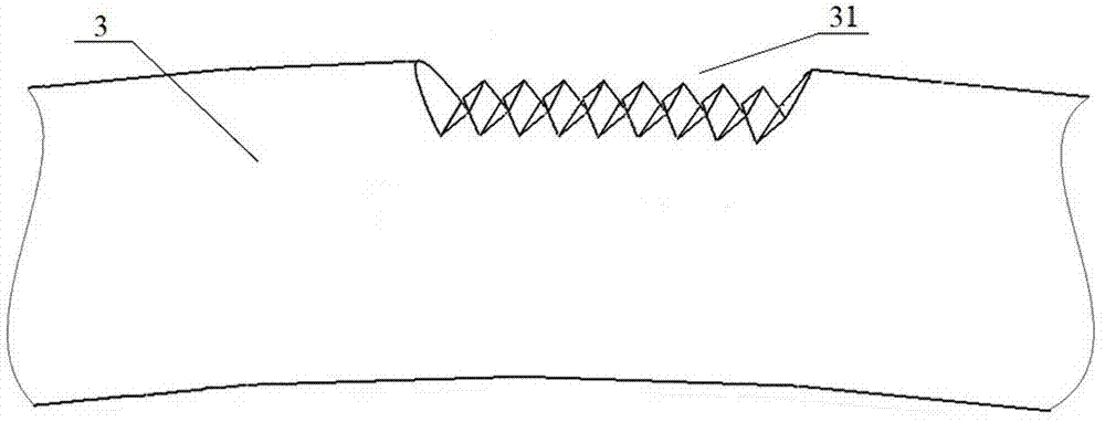
[0019] An embodiment of the optical fiber displacement detection device in the present invention is as Figure 1~Figure 2 As shown, it is a light intensity modulation type optical fiber displacement detection device, which includes an optical fiber displacement sensor and a signal processing device, wherein the signal processing device includes an optical receiver, an analog signal processing system and a data processing system.

[0020] The optical fiber displacement sensor includes an optical fiber 3, the input end of the optical fiber 3 is connected with the optical transmitter 2, the optical transmitter 2 is connected with the optical transmitter drive circuit and the modulation circuit 1, and the optical transmitter 2 is driven by the optical transmitter drive and the modulation circuit 1 Down can emit sine wave modulated optical signal; the output end of the optical fiber 3 is connected with the optical receiver 5, and the optical receiver 5 is connected to convert the op...


PUM


Abstract

The invention relates to a fiber displacement sensor, a fiber displacement detection device and a fiber for sensor. The fiber displacement sensor comprises a fiber having a bendable section. The fiber core for transmitting light waves of the fiber is provided with a light leakage hole for enabling a part of the light waves to be leaked at the bendable section of the fiber, and at the place of the same curvature radius when the bendable section bends, the light leakage hole faces to the direction same with the direction of the curvature radius or opposite to the direction of the curvature radius. The fiber displacement sensor further comprises a fiber deformation device for enabling the curvature of the bendable section to change according to the displacement change of two objects having relative displacement. When the two objects having relative displacement have displacement change, the fiber deforms under the action of the fiber deformation device, and the light leakage hole can enable the light intensity of the fiber to change obviously when the bending condition of the fiber changes, thereby realizing improvement of system detection sensitivity, reducing fiber cost, and reducing the cost of matched wavelength processing equipment; and production, debugging and maintenance are done conveniently.

Description

technical field [0001] The invention relates to an optical fiber displacement sensor, an optical fiber displacement detection device and an optical fiber for the sensor. Background technique [0002] Most traditional sensors are mainly sensors based on electromagnetic technology, which cannot be used in strong electromagnetic interference environments and the detection of flammable and explosive gases. One of the most important advantages of modern optical fiber is its flexibility and anti-magnetic and anti-explosion performance. When the bending state of the optical fiber changes, it will cause mode coupling in the optical fiber, and some of the guided wave modes become radiation modes, thereby causing bending. Loss, the smaller the bending radius, the greater the bending loss, so the light intensity modulation optical fiber sensor is made by using the bending loss principle of the optical fiber to overcome the shortcomings of the traditional sensor. [0003] In recent yea...

Claims


Application Information

Patent Timeline
IPC IPC(8): G01B11/02
Inventor 孙银山尹军华狄海廷张文涛于维娟张一茗张高潮李环宋敬国孙花枝
Owner STATE GRID CORP OF CHINA
Learn More