

Laser welding method and laser welding product
A technology of laser welding and laser beam, applied in laser welding equipment, welding equipment, metal processing equipment, etc., can solve the problems of high reflectivity and low laser energy absorption rate, achieve good absorption, increase absorption rate, high strength and The effect of stability
- Summary
- Abstract
- Description
- Claims
- Application Information
AI Technical Summary
Problems solved by technology
Method used
Image

Examples
Embodiment Construction
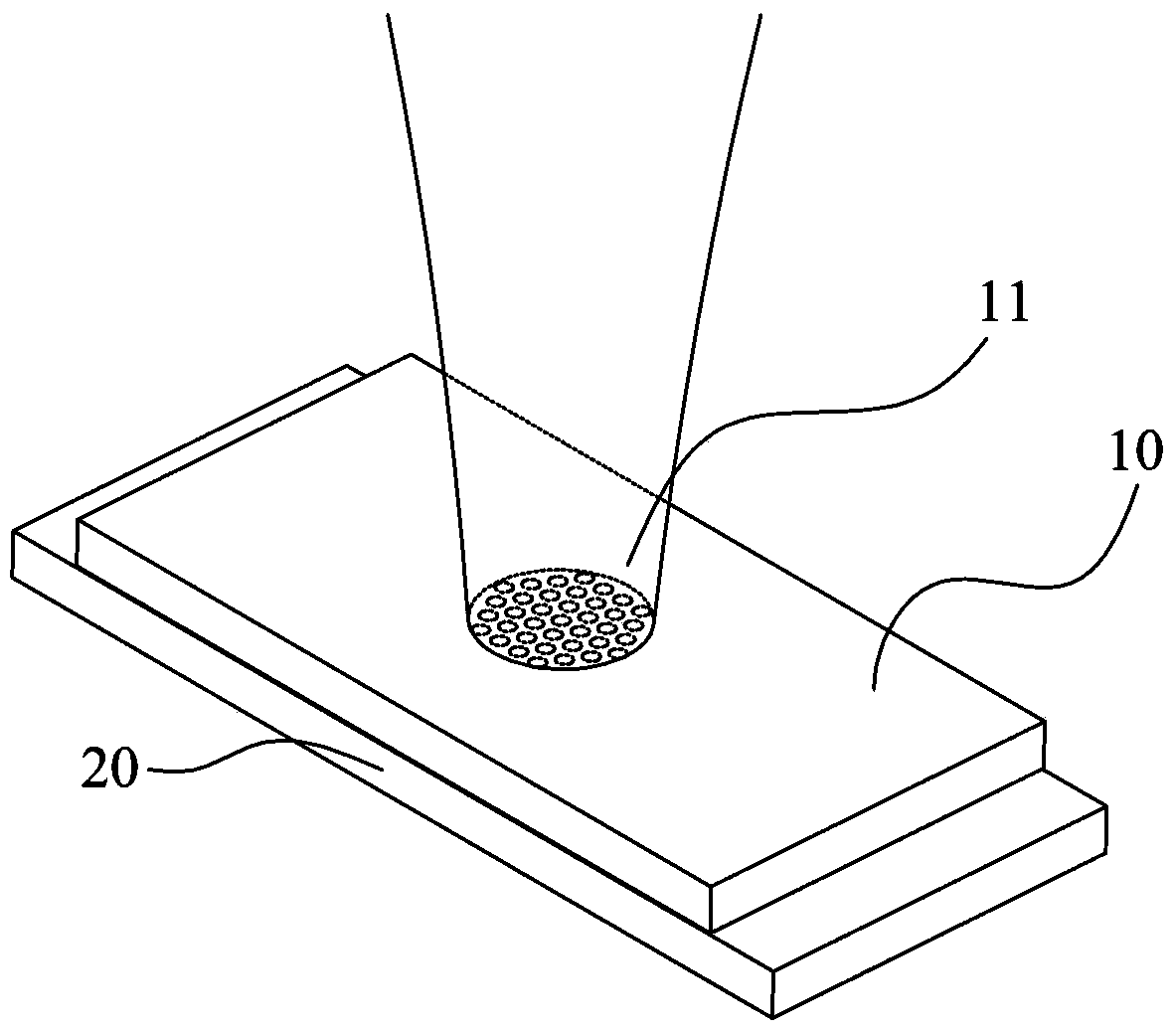
[0050] figure 1 A first embodiment of the invention is shown in which the first workpiece 10 and the second workpiece 20 are welded together with a laser beam by laser welding, in particular by laser spot welding.
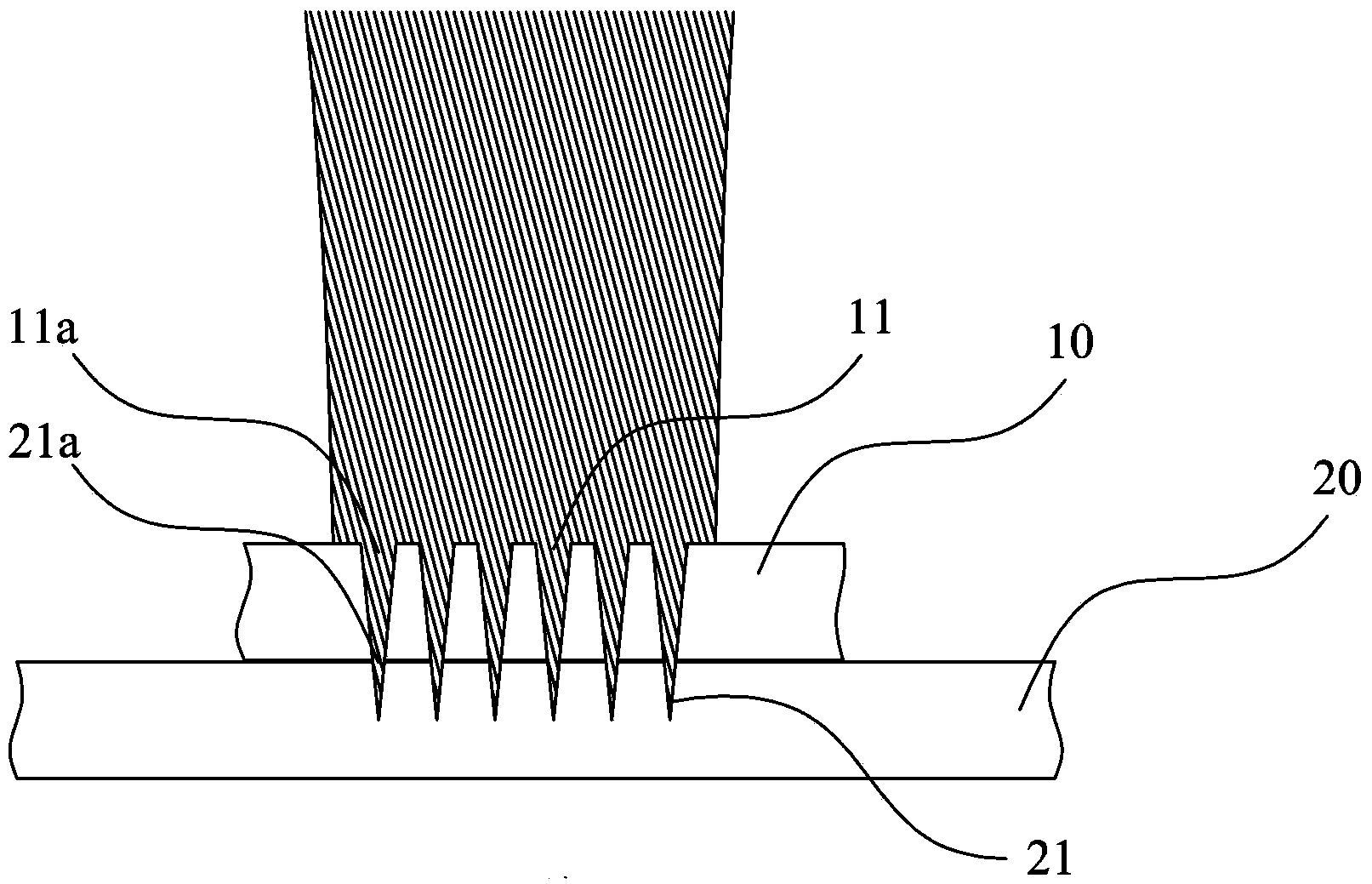
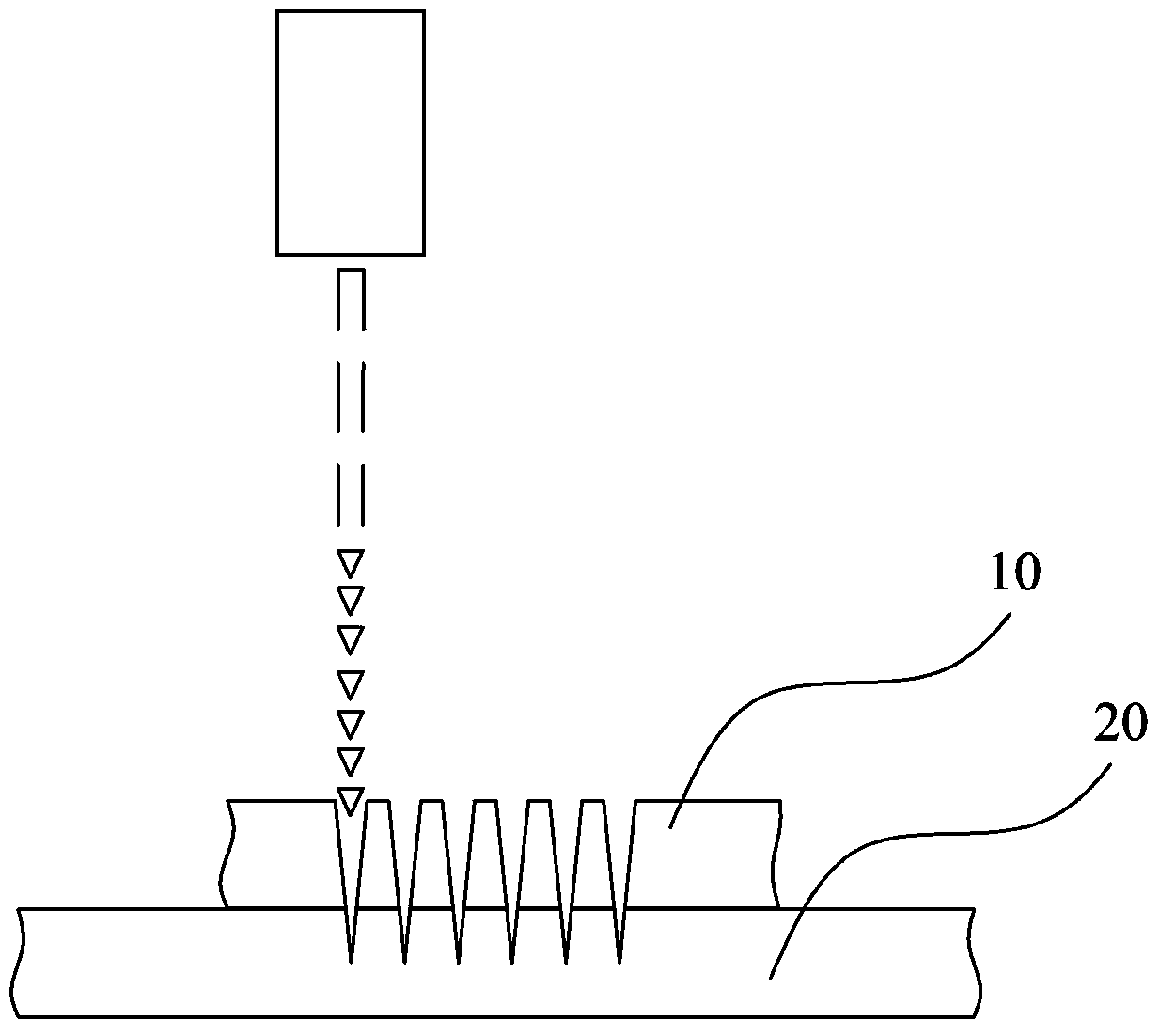
[0051]In the first embodiment, both the first workpiece 10 and the second workpiece 20 have a plate shape. Before laser welding, the first microporous structure 11 is pre-processed on the first workpiece 10, and the first microporous structure 11 is composed of a plurality of first holes 11a in the form of through holes; in addition, on the second workpiece 20 The second microporous structure 21 is also pre-processed on the upper surface, and the second microporous structure 21 is composed of a plurality of second holes 21a in the form of blind holes. Preferably, the number of the second holes 21a is equal to the number of the first holes 11a. The first microporous structure 11 and the second microporous structure 21 are positioned such that when the first workp...
PUM
 Abstract
Description
Claims
Application Information