Heat exchanger and method and apparatus for manufacturing the same

A technology for heat exchangers and manufacturing methods, applied in heat exchange equipment, indirect heat exchangers, heat exchanger types, etc., can solve problems such as slight effects, and achieve the effect of easy defrosting

Inactive Publication Date: 2015-02-11
LG ELECTRONICS INC
View PDF7 Cites 5 Cited by
  • Summary
  • Abstract
  • Description
  • Claims
  • Application Information

AI Technical Summary

Problems solved by technology

However, although the coating technology of the above-mentioned patent can prevent the frosting (implantation) of the heat exchanger to a certain extent, it has the disadvantage of little effect.

Method used


Image

  • Heat exchanger and method and apparatus for manufacturing the same
  • Heat exchanger and method and apparatus for manufacturing the same
  • Heat exchanger and method and apparatus for manufacturing the same

Examples


Embodiment Construction

[0039] Hereinafter, specific embodiments of the present invention will be described with reference to the drawings. However, the concept of the present invention is not limited to the suggested embodiments, and those skilled in the art who understand the concept of the present invention can easily propose other embodiments within the scope of the same concept.

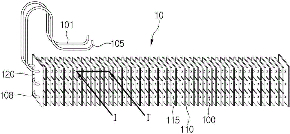
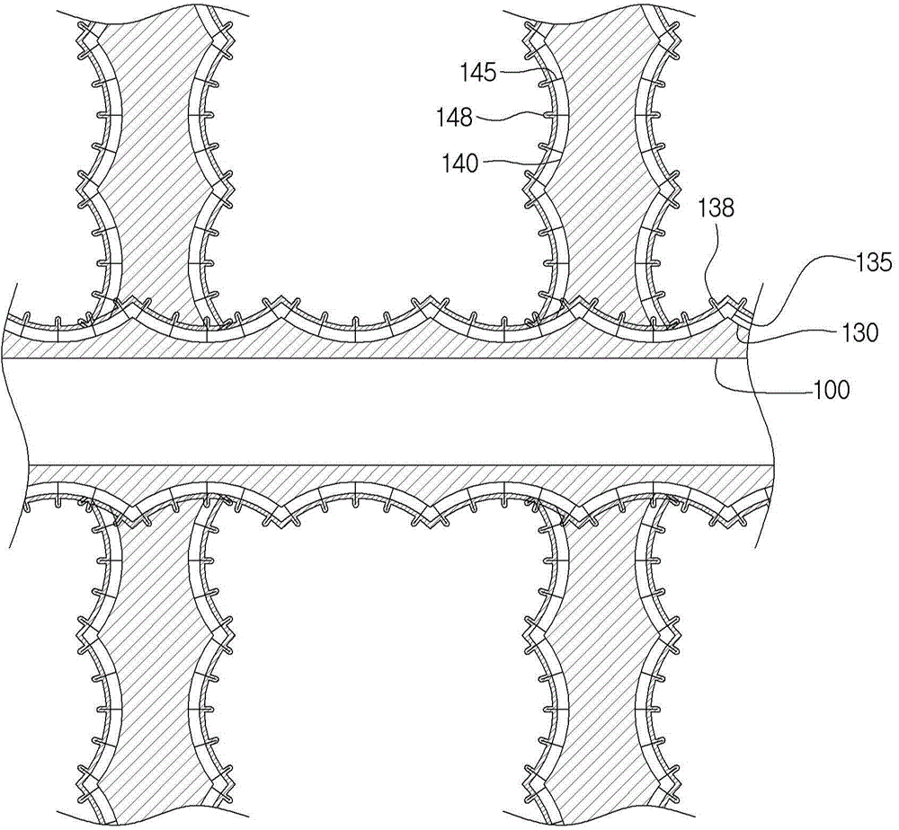
[0040] figure 1 is a diagram showing the structure of the heat exchanger of the first embodiment of the present invention, figure 2 along figure 1 The cut-away view of I-I'.

[0041] refer to figure 1 and figure 2 , The heat exchanger 10 according to the first embodiment of the present invention includes: a refrigerant pipe 100 in which the refrigerant flows; and heat exchanging fins 110 connected to the refrigerant pipe 100 . A plurality of the heat exchange fins 110 are provided, and the refrigerant tubes 110 can be connected to the heat exchange fins 110 in a manner of being arranged in a plurality of rows. ...


PUM

PropertyMeasurementUnit
thicknessaaaaaaaaaa

Abstract

A heat exchanger (10) and a method and apparatus for manufacturing the same are provided. The heat exchanger (10) includes a refrigerant tube (100) through which a refrigerant flows, a heat-exchange fin (110) into which the refrigerant tube (100) is inserted, a plurality of tube treatment parts (130, 135, 138) laminated on a surface of the refrigerant tube (100), and a plurality of fin treatment parts (140, 145, 148) laminated on a surface of the heat-exchange fin (110).

Description

technical field [0001] The present invention relates to a heat exchanger, its manufacturing method and manufacturing device. Background technique [0002] A heat exchanger is a component that constitutes a refrigeration cycle and can be used in electronic products that need to drive a refrigeration cycle, such as refrigerators and air conditioners. [0003] The heat exchanger includes: refrigerant piping through which refrigerant flows; and heat exchange fins connected to the refrigerant piping to perform heat exchange between the refrigerant and air. The heat exchange fins are connected to the refrigerant pipes to increase the heat exchange area between the refrigerant and air. [0004] A heat exchanger can function as a condenser or an evaporator. When the above-mentioned heat exchanger functions as a condenser, the high-pressure refrigerant compressed in the compressor can flow through the refrigerant pipe to exchange heat (radiate heat) with the air, thereby to conden...

Claims


Application Information

Patent Timeline
Patent Type & Authority Applications(China)
IPC IPC(8): F25B39/00
CPCB21D53/022F28F21/084F28F19/006F28F19/06F28F1/12F25B39/00F25B47/006F28F2245/04F28F13/187F28F17/005F28D1/0477F28F1/32F28F2255/20F28D2021/007F28D2021/0071C23C22/02C23C22/74C23C22/78C23C2222/20Y10T29/49378Y10T29/53113F28F13/18F28F19/00Y02T50/60
Inventor 宋贤洙李将石池成
Owner LG ELECTRONICS INC
Why Eureka
Try Eureka