Integrated optimization method and system for static model of fully-extending boom of crane
A static model and optimization method technology, applied in special data processing applications, instruments, electrical digital data processing, etc., can solve problems such as inability to obtain design solutions, achieve good results, and reduce the overall volume
- Summary
- Abstract
- Description
- Claims
- Application Information
AI Technical Summary
Problems solved by technology
Method used
Image

Examples
Embodiment 1
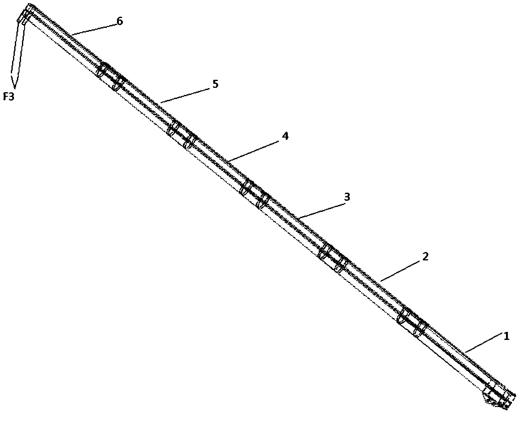
[0046] figure 1 A schematic diagram of telescopic boom modeling is shown.
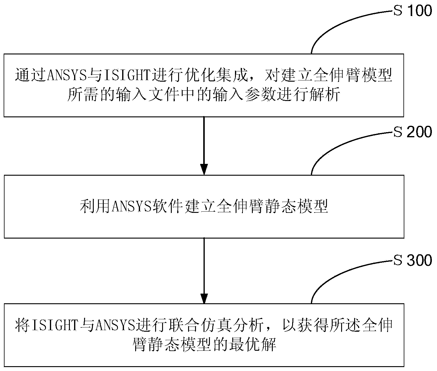
[0047] figure 2 A flow chart showing the steps of an integrated optimization method for a static model of a crane's full-reach boom.
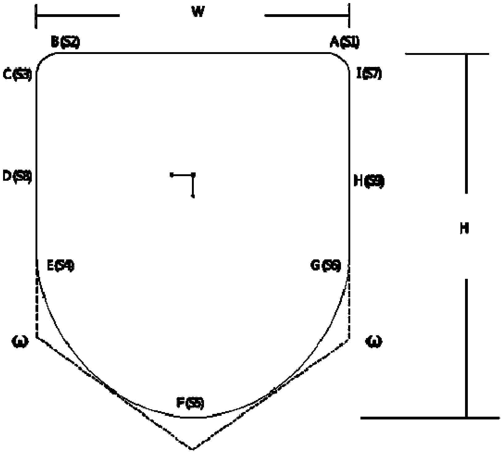
[0048] image 3 A basic boom section NURBS plot of the boom is shown.
[0049] Such as figure 1 and figure 2 As shown, an integrated optimization method of a static model of a crane full extension arm of the present invention includes:
[0050] Step S100, optimize and integrate ANSYS and ISIGHT, and analyze the input parameters in the input file required to establish the full outrigger model; Step S200, use ANSYS software to establish a full outrigger static model; and Step S300, integrate ISIGHT and ANSYS Co-simulation analysis is carried out to obtain the optimal solution of the fully extended boom static model.
[0051] The specific implementation manner of optimizing and integrating ANSYS and ISIGHT is as follows: said ANSYS is optimizing and integrating IS...
Embodiment 2
[0116] An integrated optimization system for a static model of a crane's fully extended boom on the basis of Embodiment 1, including:
[0117] The design variable acquisition unit optimizes and integrates ANSYS and ISIGHT, and analyzes the input parameters in the input file required to establish the static model of the full outrigger to obtain the design variables.
[0118] As for the modeling unit, the static model of the full extension arm is established through ANSYS software.
[0119] The output unit performs joint simulation analysis of ISIGHT and ANSYS to obtain the optimal solution of the static model of the full extension arm.
[0120] The input files used in this fully extended boom static model were obtained from the described design variables.
[0121] The output unit is adapted to analyze the output file after the co-simulation analysis, obtain the target value of the volume objective function required for the optimization of the full extension arm, and the constr...
PUM
| Property | Measurement | Unit |
|---|---|---|
| Tensile strength | aaaaa | aaaaa |
Abstract
Description
Claims
Application Information
PatSnap Eureka turns technology decisions into work you can execute. Powered by our Innovation Knowledge Graph, it runs expert workflows across engineering, life sciences, materials and intellectual property. Get your review-ready output in minutes.


