Novel hole pattern for implementing rolling of bar with large strain at core part

A technology of large strain and pass type, which is applied in the direction of metal rolling, metal rolling, rolling mill control devices, etc., can solve the problems of restricting production efficiency and metal flow performance, low strain in the center of the material, and large cross-sectional strain gradient distribution. , to achieve the effect of preventing the occurrence of defects in the center, large strain at the corners, and uniform plastic strain on the cross-section

Inactive Publication Date: 2015-02-18
YANSHAN UNIV
View PDF4 Cites 6 Cited by
  • Summary
  • Abstract
  • Description
  • Claims
  • Application Information

AI Technical Summary

Problems solved by technology

[0003] However, the traditional pass design is restricted by factors such as biting conditions, width and shape control, and the main goal is to obtain the geometric dimensions of the bar product, and seldom involves the material structure and properties; the connection is mostly determined by empirical formulas and trial-and-error methods. The basic parameters of the rolling pa

Method used


Image

  • Novel hole pattern for implementing rolling of bar with large strain at core part
  • Novel hole pattern for implementing rolling of bar with large strain at core part
  • Novel hole pattern for implementing rolling of bar with large strain at core part

Examples


Embodiment 1

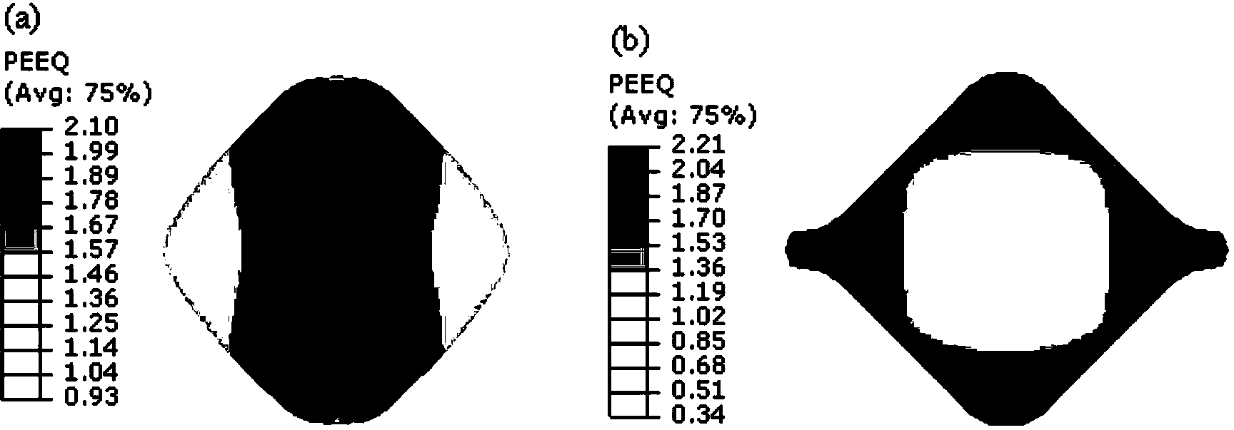
[0045] It is mainly to analyze the traditional pass system, that is, figure 2 with image 3 Shown, form comparative analysis with embodiment 2, highlight the advantage of the novel pore structure of the present invention. Wherein, the size of the incoming material and each model parameter are the same as those in Example 2, and rolled into a square steel with a variable length of 17 mm after six passes of water chestnut / square and four passes of square / square.

Embodiment 2

[0047] The square steel with a side length of 24 mm, a length of 800 mm and a chamfer radius of 6 mm is rolled into a square steel with a side length of 17 mm through two passes. which is Figure 4 For the second group of trial pass patterns shown, here we focus on the specific shape design process of the new pass pattern concave-bottom ellipse in the first pass, while the traditional pass patterns for other passes are omitted.

[0048] And choose a reasonable pass size, the pass parameter value is calculated as follows:

[0049] ①The first group of pass system

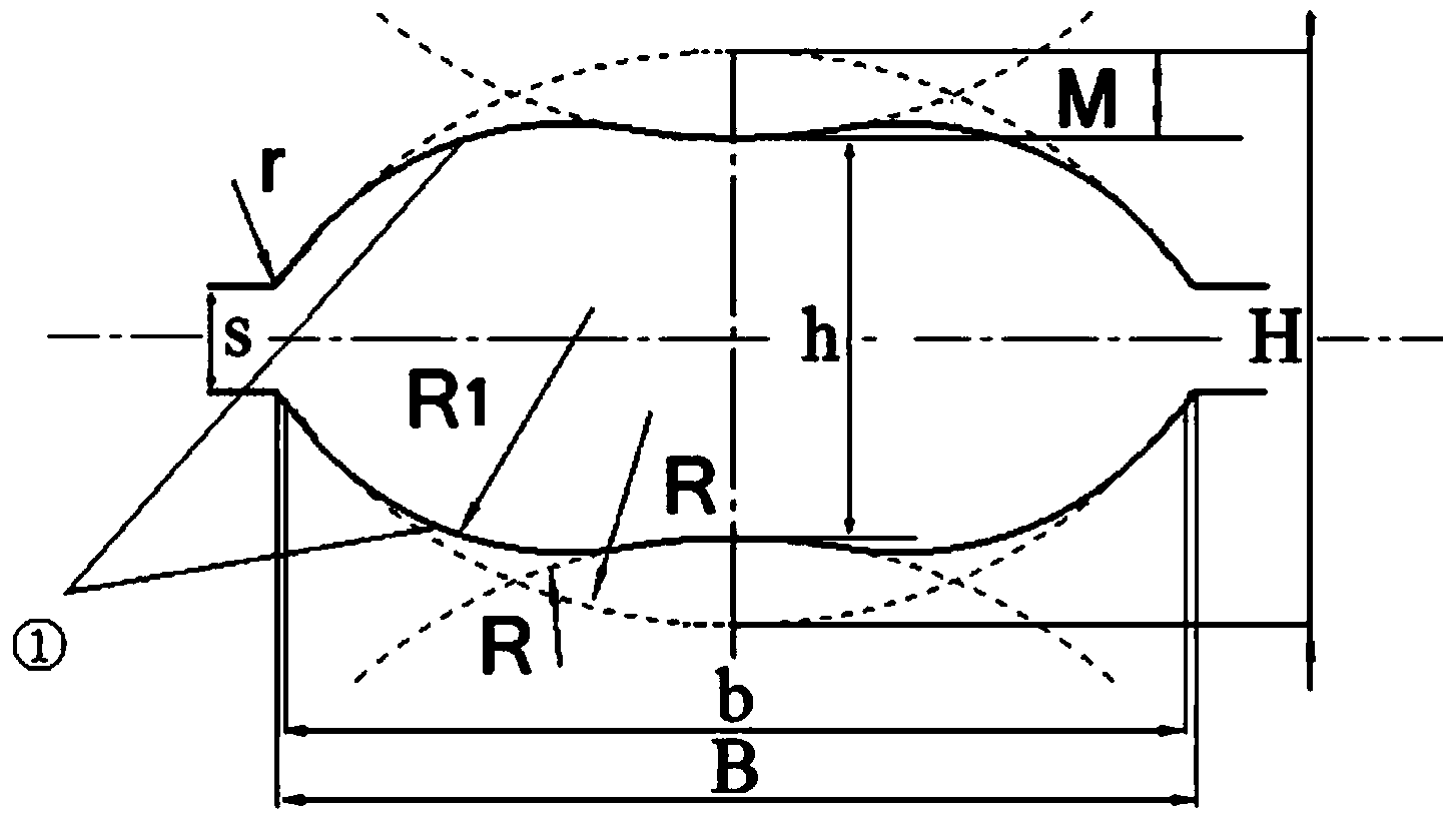
[0050] 1. The first pass (new type convex ellipse)

[0051] Take H=22, β=1.0, M=2

[0052] h=H-2M=22-4=18

[0053] B=a+(a-h)β=24+(24-18)=30

[0054] s=(0.2~0.3)h=4

[0055] R=17

[0056] r=(0.08~0.12)B=3

[0057] R 1 =5.74

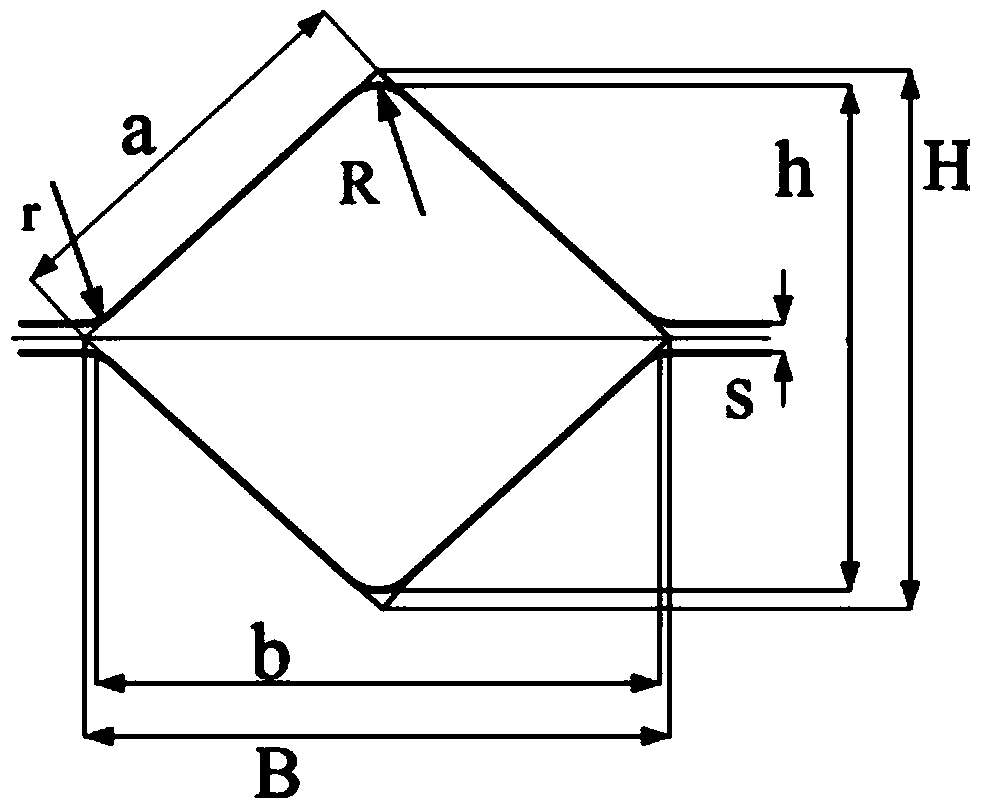
[0058] 2. The second pass (square hole type)

[0059] Take a=17.5

[0060] h=1.41a=24.68

[0061] R=5; r=5

[0062] h=24.68-0.83R=20.53

[0063] b=24.68-2=22.68

[0064] s≈0.1a≈2

[...


PUM


Abstract

The invention discloses a novel hole pattern for implementing rolling of a bar with a large strain at a core part. The hole pattern adopts a convex oval structure; the upper part and the lower part of the structure are symmetric, and the left part and the right part are symmetric; the hole pattern comprises a first outer chamfering arc R, and a second outer chamfering arc R1, wherein the second outer chamfering arc R1 is externally tangent with the two sides of the first outer chamfering arc R; the other end of the second outer chamfering arc R1 is transitional to a notch plane of a roller gap through the inner chamfering arc r; the included angle between the second outer chamfering arc R1 and the notch plane is obtuse; the ratio of the long axis to the short axis of the convex oval structure is 3:1. The novel hole pattern for implementing rolling of the bar with the large strain at the core part is favorable to obtain the bar with the large strain, improve the combination properties of the material, and gradually guide the large strain to the core part of the product; compared with the conventional hole pattern with the small strain at the core part and the large strain at the corner part, the novel hole pattern is more favorable to compact the core part and prevent defects at the core part; meanwhile, the novel hole pattern can generate the large accumulated strain, and meanwhile, reduce the gradient change of the strain at the fracture surface; the rolled piece is uniform in multidirectional deformation; the broadsiding amount is increased, the rolling turns can be reduced, the production efficiency can be improved, and the prevention of ear defect can be facilitated.

Description

technical field [0001] The invention belongs to the field of pass design and development of metallurgical technology, in particular to a novel pass that realizes the rolling of large-strain bars at the core. technical background [0002] The pass design is the core link in the production of section steel. It is directly related to the rationality of metal plastic flow and the microstructure and properties of rolled products, and the pass rolling bar technology itself has a large strain of multi-pass and multi-directional simultaneous processing. characteristic. [0003] However, the traditional pass design is restricted by factors such as biting conditions, width and shape control, and the main goal is to obtain the geometric dimensions of the bar product, and seldom involves the material structure and properties; the connection is mostly determined by empirical formulas and trial-and-error methods. The basic parameters of the rolling pass and the series configuration metho...

Claims


Application Information

Patent Timeline
IPC IPC(8): B21B19/02B21B37/16
Inventor 李学通史喜帅王敏婷杜凤山
Owner YANSHAN UNIV
Why Eureka
Try Eureka