Fin-angle feedback device and mounting method thereof

A feedback device and fin angle technology, applied in the field of fin stabilization equipment, can solve the problems of less fin angle, little research on structure optimization and improvement, narrow market demand, etc., to reduce assembly time, facilitate assembly, and have a simple structure. Effect

Active Publication Date: 2015-02-18
CHONGQING HUAYU HEAVY IND ELECTROMECHANICAL CO LTD
View PDF4 Cites 5 Cited by
  • Summary
  • Abstract
  • Description
  • Claims
  • Application Information

AI Technical Summary

Problems solved by technology

The main reasons for the lack of fin angle patents are: 1) The fin angle feedback device is a part of the fin stabilizer, and the research units of the fin stabilizer are only Harbin Engineering University and the 704th Research Institute, and t...

Method used


Image

  • Fin-angle feedback device and mounting method thereof
  • Fin-angle feedback device and mounting method thereof
  • Fin-angle feedback device and mounting method thereof

Examples


Embodiment

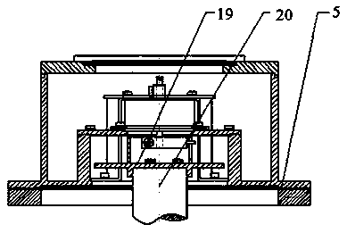
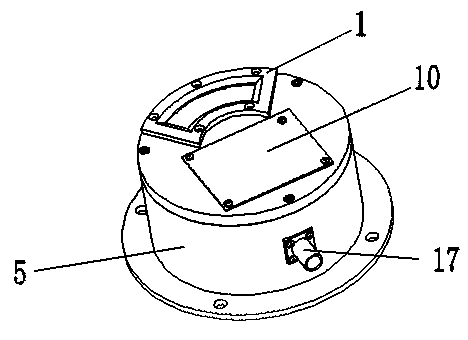
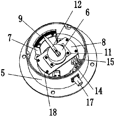
[0037] A fin angle feedback device such as Figure 1~7 As shown, including fin stabilizer, feedback body and coupling 19;

[0038] The feedback body includes a housing 5, a potentiometer 6, a pointer 12, and a transmission rod 13; the housing 5 is composed of an integrally formed bottom plate and side walls, and the bottom plate and side walls form an accommodating cavity with an upper end opening, and the edge of the bottom plate is along the side The circumference of the wall extends outward horizontally to form a flange, and the middle part of the bottom plate is also provided with an installation opening that can freely pass through the coupling; the potentiometer 6, the pointer 12 and the transmission rod 13 are all installed in the shell 5 In the housing chamber; wherein, the potentiometer 6 is fixedly installed in the housing chamber at the position directly above the installation opening on the bottom plate with its handle vertically arranged, and the handle of the pot...


PUM


Abstract

A fin-angle feedback device comprises a fin stabilizer, a feedback main body and a coupler, wherein the feedback main body comprises a housing, a potentiometer, a pointer and a transmission rod, wherein a notch is formed in the side wall of an upper end shaft sleeve of the coupler; the upper end shaft sleeve of the coupler penetrates a mounting opening in a baseplate to extend into an accommodating cavity of the housing; a shift lever of the transmission rod is clamped into the notch; the feedback main body is fixed to the fin stabilizer through a flange plate; a lower end shaft sleeve of the coupler is fixed to a fin shaft of the fin stabilizer in a sleeving manner. The fin-angle feedback device is simple in structure; all components of the feedback main body can be mounted on the housing of the feedback main body, so that the feedback main body can be assembled into an independent whole; the fin-angle feedback device is convenient to assemble and suitable for batch production. A mounting method of the fin-angle feedback device comprises the steps of assembling components into an integral feedback main body and then the feedback main body is directly mounted on the fin shaft through the coupler. The assembly process is simple, and the assembly time is helped to be shortened during batch production of the fin-angle feedback device.

Description

technical field [0001] The invention belongs to the field of fin stabilizer equipment, in particular to a fin angle feedback device. Background technique [0002] The stabilizer fins are installed in the bilge of the two sides of the ship, and the section is wing-shaped, also known as side rudder. The fin stabilizer is rotated by the operating mechanism, so that the water flow exerts force on it, thereby forming an anti-rolling moment and reducing the sway, so as to reduce the roll of the hull. The fin stabilizer is composed of three parts: actuator, hydraulic system and control system. Among them, the control system generally adopts the fin angle feedback control method. [0003] The traditional fin angle feedback device includes a fin stabilizer, a feedback body and a coupling; the shell of the feedback body is installed on the fin stabilizer, and the feedback body includes a shell, a dial, a pointer, a potentiometer, a proximity switch, etc. Among them, many parts of t...

Claims


Application Information

Patent Timeline
IPC IPC(8): B63B39/06
Inventor 黄仲华赵林罗小燕王鑫鹏申林红
Owner CHONGQING HUAYU HEAVY IND ELECTROMECHANICAL CO LTD
Why Eureka
Try Eureka