
A lifting and rotating platform system for a three-dimensional garage

A lifting and rotating, three-dimensional garage technology, which is applied in the direction of buildings, building types, buildings, etc. where cars are parked, can solve problems such as difficult implementation, multiple power sources, and slow transmission speed, and achieve improved service life and stability. Stability and lifting speed, the effect of improving the utilization rate of land

Active Publication Date: 2017-06-09
王景保
View PDF1 Cites 1 Cited by
  • Summary
  • Abstract
  • Description
  • Claims
  • Application Information

AI Technical Summary

Problems solved by technology

[0003] The lifting and rotating platform in the prior art is vertically lifted by 4 motors through chain traction. The 4 motors need to work synchronously, and the timing and speed of their startup and shutdown are required to be highly consistent, so that the lifting and rotating platform can run smoothly. It is difficult to achieve in actual operation, and there are many power sources and energy consumption
In addition, the chain drive has many disadvantages, such as: 1. The transmission speed is slow, which limits the running speed of the entire three-dimensional garage. The length is easy to shake, so that the lifting and rotating platform cannot run smoothly. Therefore, the use of chain transmission greatly limits the depth and capacity of the three-dimensional garage; out of sync
[0004] In addition to the above-mentioned problems, the exhaust effect of this intensive cylindrical garage is very poor. It is necessary to install a large fan and a corresponding ventilation system to replace the air inside the garage, which will greatly increase the difficulty of construction and the garage. construction cost

Method used


Image

  • A lifting and rotating platform system for a three-dimensional garage
  • A lifting and rotating platform system for a three-dimensional garage
  • A lifting and rotating platform system for a three-dimensional garage

Examples


Embodiment Construction

[0026] The present invention will be further described in detail below in conjunction with the accompanying drawings and specific embodiments.

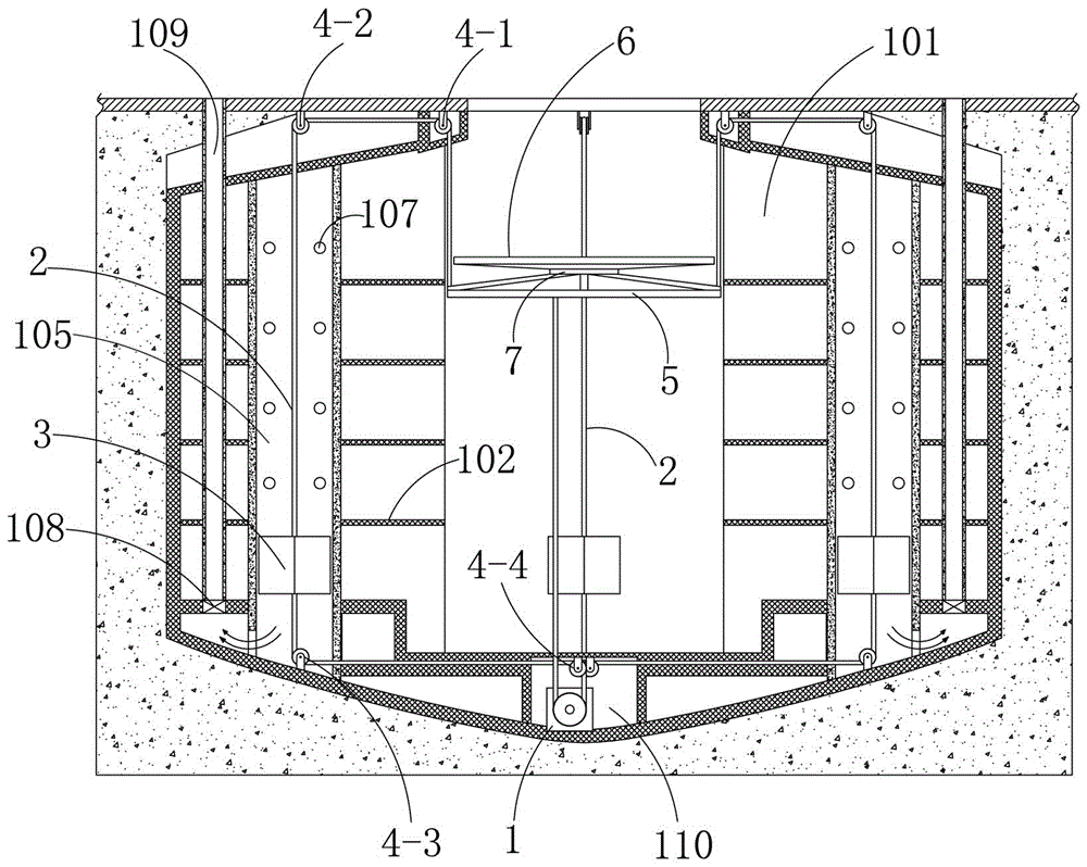
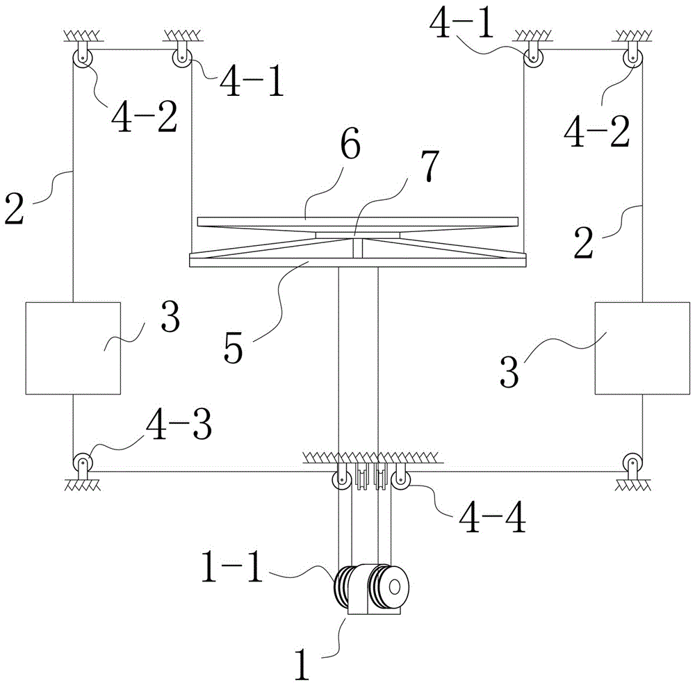
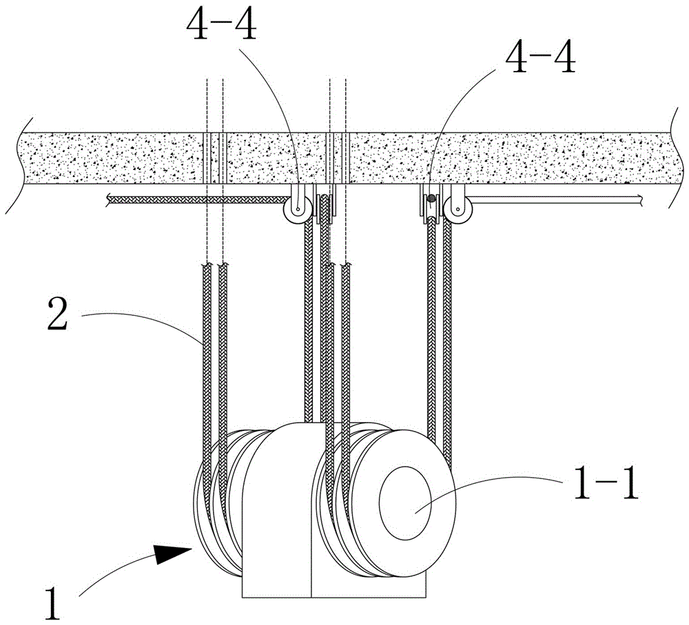
[0027] Attached below Figure 1-7 The present invention is further described in detail with specific embodiments.

[0028] as attached Figure 1-7 A lifting and rotating platform system for a three-dimensional garage is shown, which includes a lifting and rotating platform for parking cars and a traction mechanism that drives the lifting and rotating platform to lift vertically. A traction machine 1, at least three suspension cables 2 driven by the traction machine 1, a counterweight 3 arranged on the suspension cables 2, and a suspension cable 2 turned on the wall of the garage shaft 101 One end of the suspension steel cable 2 is fixedly connected to the lifting and rotating platform, and the other end is fixedly connected to the bottom of the lifting and rotating platform by bypassing the guiding fixed pulley and the traction shea...


PUM


Abstract

The present invention relates specifically to a lifting and rotating platform system for a three-dimensional garage, which belongs to the technical field of three-dimensional parking garages. The mechanism includes a traction machine set in the center of the bottom of the garage shaft, a suspension cable driven by the traction machine, a counterweight, and a guide fixed pulley block that turns the suspension cable. One end of the suspension cable is connected to the lifting and rotating platform. It is fixedly connected, and the other end bypasses the guide fixed pulley block and the traction wheel of the traction machine and is fixedly connected with the bottom of the lifting and rotating platform. The invention uses a traction machine and a plurality of suspension steel cables to drive the entire lifting and rotating platform to move vertically, which can greatly improve the operating speed of the lifting and rotating platform, reduce the waiting time of users, and meet the needs of deeper three-dimensional garages. Use it to help expand the capacity of the garage, improve the utilization rate of the land, and save land resources.

Description

technical field [0001] The invention relates to the technical field of lifting equipment for a three-dimensional parking garage, in particular to a lifting and rotating platform system for a three-dimensional garage. Background technique [0002] At present, with the intensification of the urbanization process, the permanent population of the city is increasing, and the available land area in the city is getting less and less. With the development of the country, there are more and more household vehicles, so parking has become an important problem that plagues people's normal life and work in the city. For this reason, in recent years there has been a cylindrical three-dimensional parking garage built underground, such as the disclosed cylindrical combined intensive three-dimensional parking garage in the Chinese invention patent No. 200610086606.7, which transports vehicles to park or take out by lifting and rotating platforms. Greatly save the floor area of ​​the garage....

Claims


Application Information

Patent Timeline
Patent Type & Authority Patents(China)
IPC IPC(8): E04H6/28
Inventor 王景保王洋
Owner 王景保
Learn More