
Micro grid energy storage device design method based on capacity limit value constrain

A technology of energy storage device and design method, which is applied in the direction of calculation, instrumentation, data processing, etc., and can solve problems such as difficulty in satisfying smooth power, redundant or insufficient configuration capacity of energy storage devices, failure to achieve expected control goals, etc.

Inactive Publication Date: 2015-02-18
ELECTRIC POWER RES INST OF GUANGDONG POWER GRID
View PDF11 Cites 17 Cited by
  • Summary
  • Abstract
  • Description
  • Claims
  • Application Information

AI Technical Summary

Problems solved by technology

[0014] In the actual planning of the existing microgrid, the above two forms are mostly used alone, and have not been considered comprehensively
Therefore, the configuration of energy storage devices in the prior art is difficult to meet the multi-objective requirements of smoothing power and peak shaving and valley filling at the same time.
Conventional methods will, to a certain extent, cause more or less redundancy or insufficiency in the capacity of the energy storage device configuration, thus affecting the economics of the energy storage device configuration
The construction of micro-grids in the prior art often uses single constraints such as smooth power or energy management to formulate the capacity of energy storage devices with the goal of economy, and it is difficult to meet the multi-objective requirements of smooth power and peak shaving and valley filling.
If the goal is only to smooth power, there will be a problem that the capacity of the energy storage device is too small to achieve the expected control target during the annual operation; Plant capacity is idle, adding unnecessary construction and operating costs

Method used

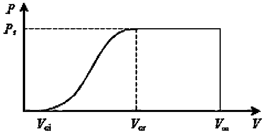
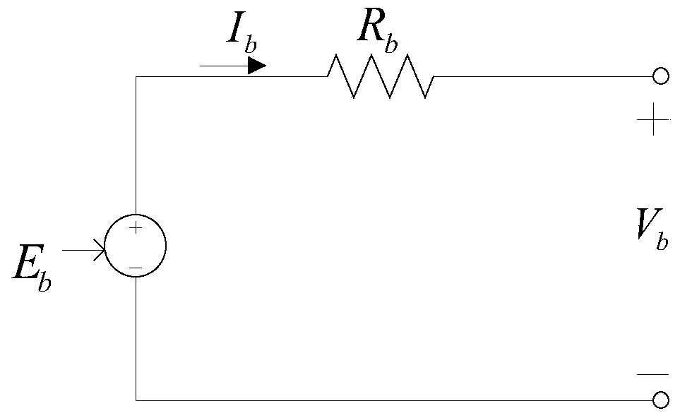

Image

  • Micro grid energy storage device design method based on capacity limit value constrain
  • Micro grid energy storage device design method based on capacity limit value constrain
  • Micro grid energy storage device design method based on capacity limit value constrain

Examples


Embodiment Construction

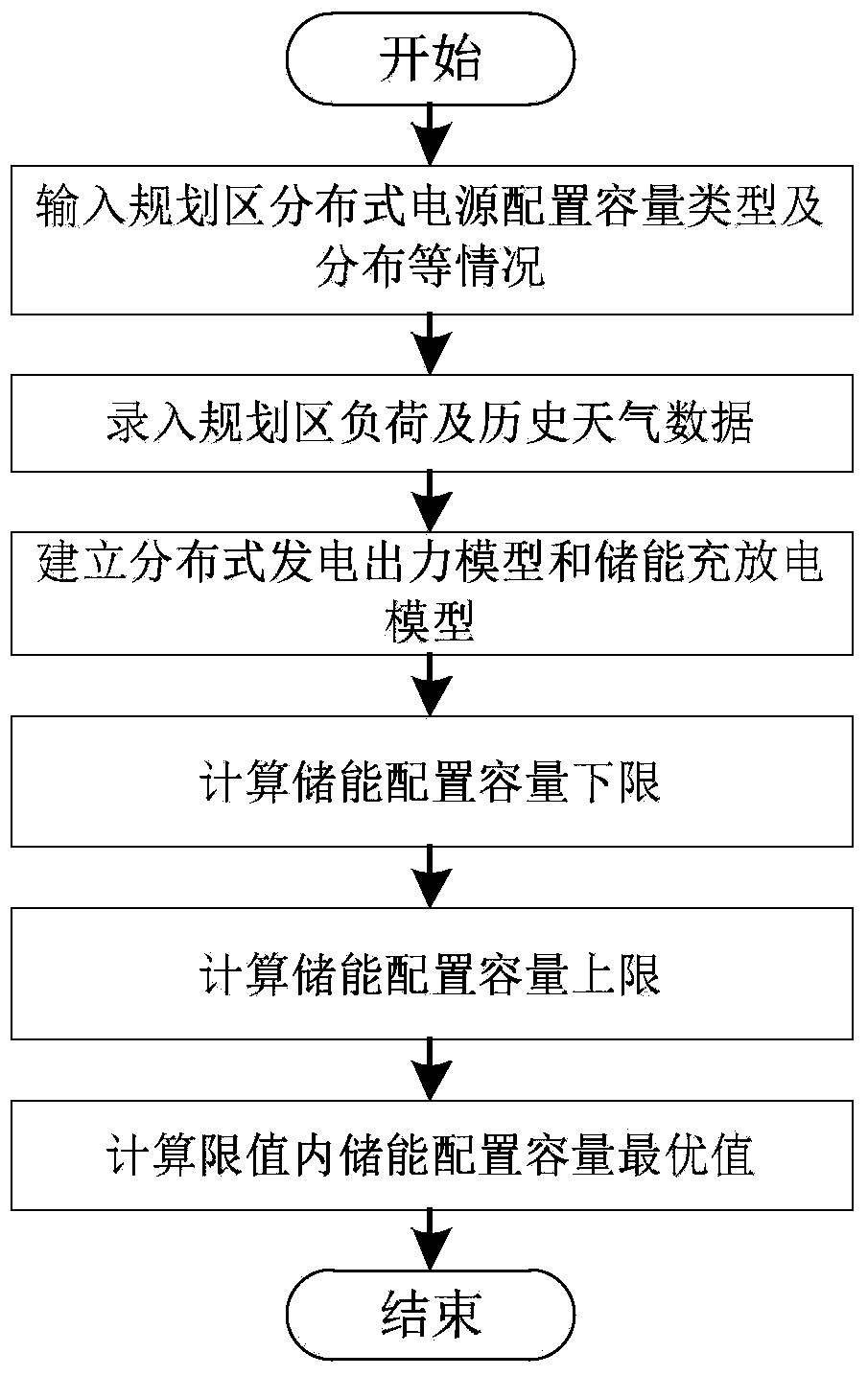
[0118] see figure 1 , an embodiment of the method for designing a micro-grid energy storage device based on capacity limit constraints of the present invention includes the following steps:

[0119] S1, input the distributed power configuration capacity type and energy storage device type and distribution in the planning area;

[0120] S2, input planning area load and historical weather data;

[0121] S3, establishing the distributed power output model and the charging and discharging model of the energy storage device;

[0122] S4, calculating the lower limit of the configuration capacity of the energy storage device;

[0123] S5, calculating the upper limit of the configured capacity of the energy storage device;

[0124] S6. Calculate the optimal value of the configured capacity of the energy storage device within the limit.

[0125] The step S3 of establishing the distributed power output model and the charging and discharging model of the energy storage device includ...


PUM


Abstract

A micro grid energy storage device design method based on capacity limit value constrain includes 1, inputting the planning area distribution-type power supply allocation capacity and the type and distribution situation of an energy storage device; 2, inputting the planning area load and historical weather data; 3, establishing a distribution-type power supply force model and an energy storage charging and discharging module; 4, calculating the lower limit of the energy storage device allocation capacity; 5, calculating the upper limit of the energy storage device allocation capacity; 6, calculating the optimal value of the energy storage device allocation capacity in the range of the limit value. By the aid of the method, on the basis that the energy storage device capacity limit value of a connected-type micro grid is met, the optimal energy storage device capacity allocation matching with distribution type power generation is calculated, the requirements on reliability and economy of the micro grid can be met through the energy storage device capacity to the utmost extent, and clean, safe and reliable power is provided for loading.

Description

technical field [0001] The invention relates to a design method of a micro-grid energy storage device based on capacity limit constraints for the planning and design of an urban grid-connected micro-grid system. Background technique [0002] The current energy situation is tense and environmental pollution is serious. The state has issued various policies to support the transformation of the power grid and reduce the pressure on the power grid. As the load continues to grow, it puts forward higher requirements for power quality and power supply reliability. At present, the energy storage device technology is more and more favored by users because of its characteristics of storing electric energy, being able to realize peak shaving and valley filling, and smoothing power fluctuations. The system energy storage device can perform active / reactive power control, realize real-time balance of system power, and compensate for fluctuations in renewable energy, thereby improving sys...

Claims


Application Information

Patent Timeline
IPC IPC(8): G06Q10/04G06Q50/06
CPCG06Q10/04G06Q50/06Y02E40/70Y04S10/50
Inventor 张跃赵艳军杨汾艳曾杰盛超陈晓科李峰刘正超林冬孙闻唐景星王钤付聪郑扶民钟红梅刘成功王奕翁洪杰马明李玎朱良合张远
Owner ELECTRIC POWER RES INST OF GUANGDONG POWER GRID
Learn More