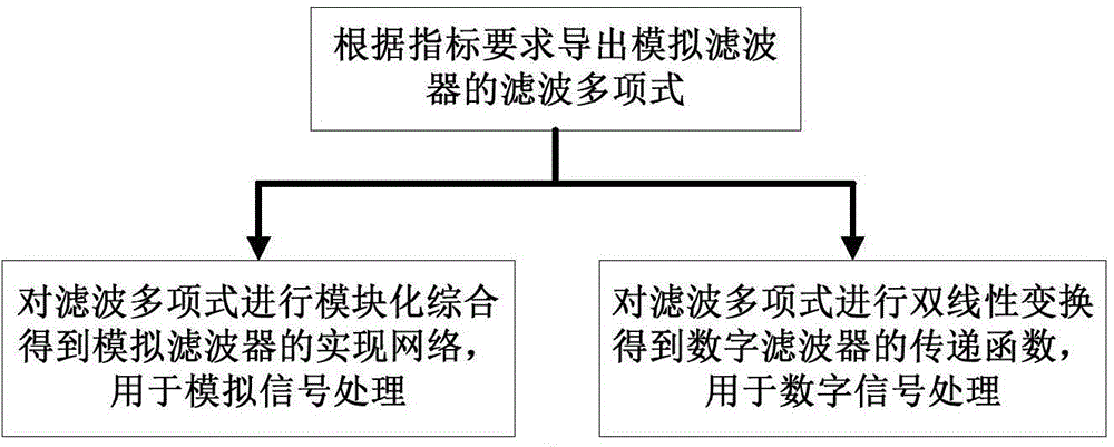
Filter direct synthetic method
A comprehensive method and filter technology, applied in the field of signal processing, can solve the problems of lack of realization structure and the inability of filter to realize complex frequency response.
- Summary
- Abstract
- Description
- Claims
- Application Information
AI Technical Summary
Problems solved by technology
Method used
Image
Examples
Embodiment 1
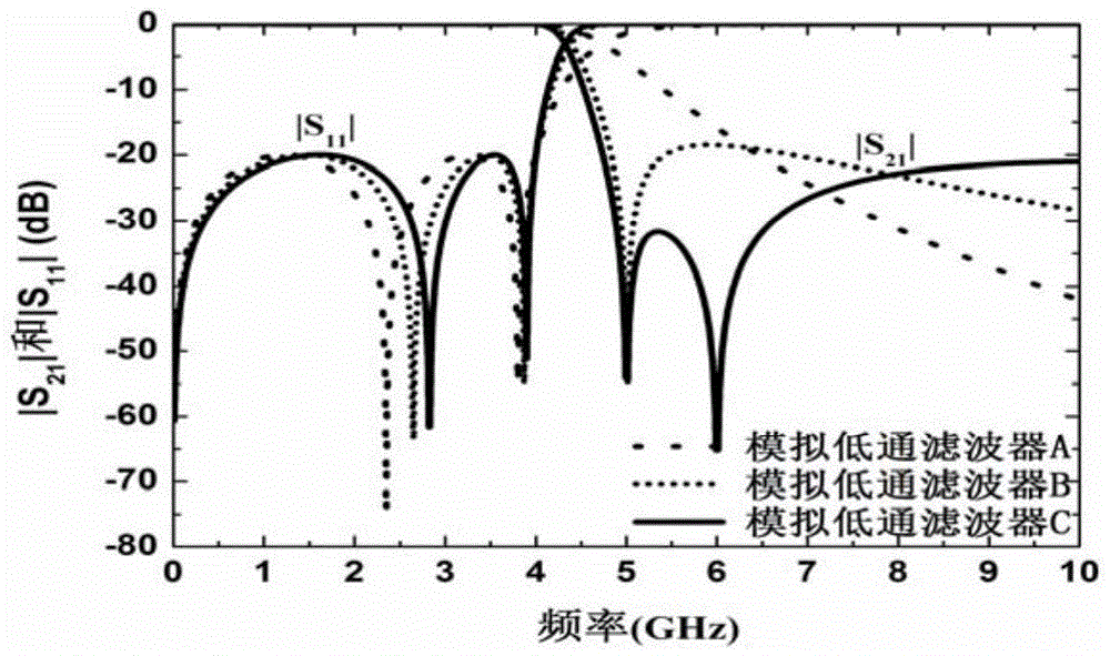
[0113] Embodiment 1 is about the synthesis of analog low-pass filters. Here, three analog low-pass filters are taken as an example, namely, analog low-pass filter A, analog low-pass filter B, and analog low-pass filter C. The pass-band cut-off frequencies of the three analog low-pass filters are all set to 4GHz, and the return loss in the pass-band is less than -20dB. In order to illustrate the superiority of the method of the present invention, that is, the performance of the analog low-pass filter can be changed by setting the transmission zero point at the specified position, so that it can flexibly meet the requirements. Three analog low-pass filters have different frequency responses ,Such as figure 2 shown. In the analog low-pass filter A, all transmission zeros can be placed at infinity, resulting in good high-frequency rejection. Its filter polynomial is as follows:
[0114] F L ( s ...
Embodiment 2
[0131] The second embodiment is about the synthesis of analog high-pass filters. For example, to design an analog high-pass filter, the initial frequency of its passband is specified as 5GHz, the return loss in the passband is lower than -20dB, one transmission zero is located at zero frequency, and the other transmission zero is set at 2GHz, its frequency response Such as Figure 6 shown. By method described in the present invention, can derive the filtering polynomial of analog high-pass filter as follows:
[0132] F H ( s ‾ ) = s ‾ 2 + 32.4126
[0133] P H ( s ‾ ) = 0.7024 s ‾ ...
Embodiment 3
[0139] The third embodiment is about the synthesis of analog bandpass filters. For example, to synthesize a third-order analog bandpass filter, its passband is located at [3.0, 5.0]GHz, the return loss in the passband is lower than -20dB, a transmission zero is located at zero frequency, and a transmission zero is located at 2.5GHz, A transmission null is located at 6.0GHz. These transmission zeros at finite frequencies can improve the frequency selectivity of the filter, whose frequency response is as Figure 9 shown. By method described in the present invention, can derive the filtering polynomial of this analog bandpass filter as follows:
[0140] P BP ( s ‾ ) = 1.9603 s ‾ 5 + 82.8218 s ‾ 3 ...
PUM
 Abstract
Description
Claims
Application Information
 - R&D
- Intellectual Property
- Life Sciences
- Materials
- Tech Scout
- Unparalleled Data Quality
- Higher Quality Content
- 60% Fewer Hallucinations
Browse by: Latest US Patents, China's latest patents, Technical Efficacy Thesaurus, Application Domain, Technology Topic, Popular Technical Reports.
© 2025 PatSnap. All rights reserved.Legal|Privacy policy|Modern Slavery Act Transparency Statement|Sitemap|About US| Contact US: help@patsnap.com


