Tiller for tea garden

A technology for cultivating machines and tea gardens, applied in the field of agricultural machinery, can solve the problems of being unsuitable, difficult to reach more than 25 centimeters, only reaching twelve or three centimeters, etc., and achieve the effects of stable transmission, simple structure and compact mechanism

Inactive Publication Date: 2015-02-25
ZHEJIANG KAWASAKI TEA MACHINERY
3 Cites 4 Cited by

AI-Extracted Technical Summary

Problems solved by technology

The traditional conventional plow is suitable for general paddy and dry field cultivation, but it is not suitable for deep plowing in tea gardens. It is difficult to reach a depth of more than 25 cm, and after plowing, the soil becomes strips or the ridges are too large to form a ditch and ridge, which is not suitable for tea gardens. deep plowin...

Abstract

The invention relates to the technical field of agricultural machines, in particular to a tiller for a tea garden. A mechanical body of the tiller for the tea garden is provided with a handle, a power mechanism, a gear box, driving wheels and a guiding wheel, the handle is located at the rear end of the mechanical body and used for being held, the driving wheels are located at the lower portion of the mechanical body and used for providing traveling power, and the guiding wheel is used for guiding when the mechanical body travels; the gear box is provided with a driving arm, a tillage arm and a connecting rod, and the power mechanism transmits power to the driving arm and the driving wheels through the gear box; the driving arm, the tillage arm and the connecting rod are connected to form a crank-connecting rod mechanism, and the tillage arm is provided with a tillage tooth used for digging soil; the tillage tooth comprises a first installation portion, two curved teeth are arranged on the first installation portion in parallel, the mechanical body is further provided with a soil crushing rod matched with the tillage tooth, the soil crushing rod is located between the two curved teeth, and the working section, matched with the tillage tooth, of the soil crushing rod is horizontal. The tiller for the tea garden is simple in structure, low in cost and suitable for deep tillage of the tea garden.

Application Domain

Technology Topic

Image

  • Tiller for tea garden
  • Tiller for tea garden
  • Tiller for tea garden

Examples

  • Experimental program(1)

Example Embodiment

[0027] Example 1
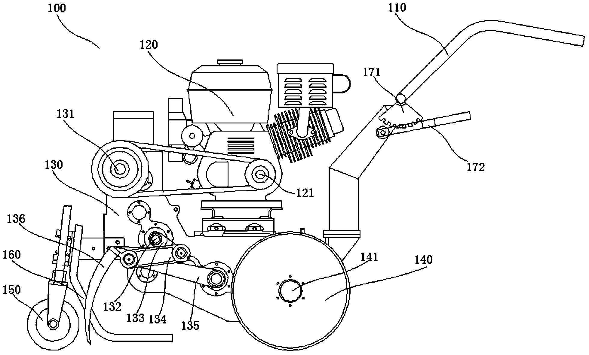
[0028] Such as figure 1 As shown, the tea plantation machine provided in this embodiment is provided with a handle 110, a power mechanism 120, a gear box 130, a driving wheel 140, and a guide wheel 150 on the mechanical body 100. The handle 110 is located at the rear end of the mechanical body 100 for supporting , The driving wheel 140 is located at the lower part of the machine body 100 for providing walking power, and the guide wheel 150 is used for guiding the machine body 100 when walking.
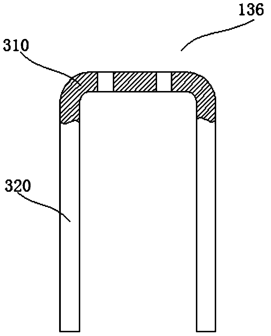
[0029] The gear box 130 is provided with a driving arm 133, a tilling arm 134, and a connecting rod 135. The power mechanism 120 transmits power to the driving arm 133 and the driving wheel 140 through the gear box 130; the driving arm 133, the tilling arm 134 and the connecting rod 135 are configured as a crank The link mechanism, the tilling arm 134 is provided with tilling teeth 136 for plowing soil.
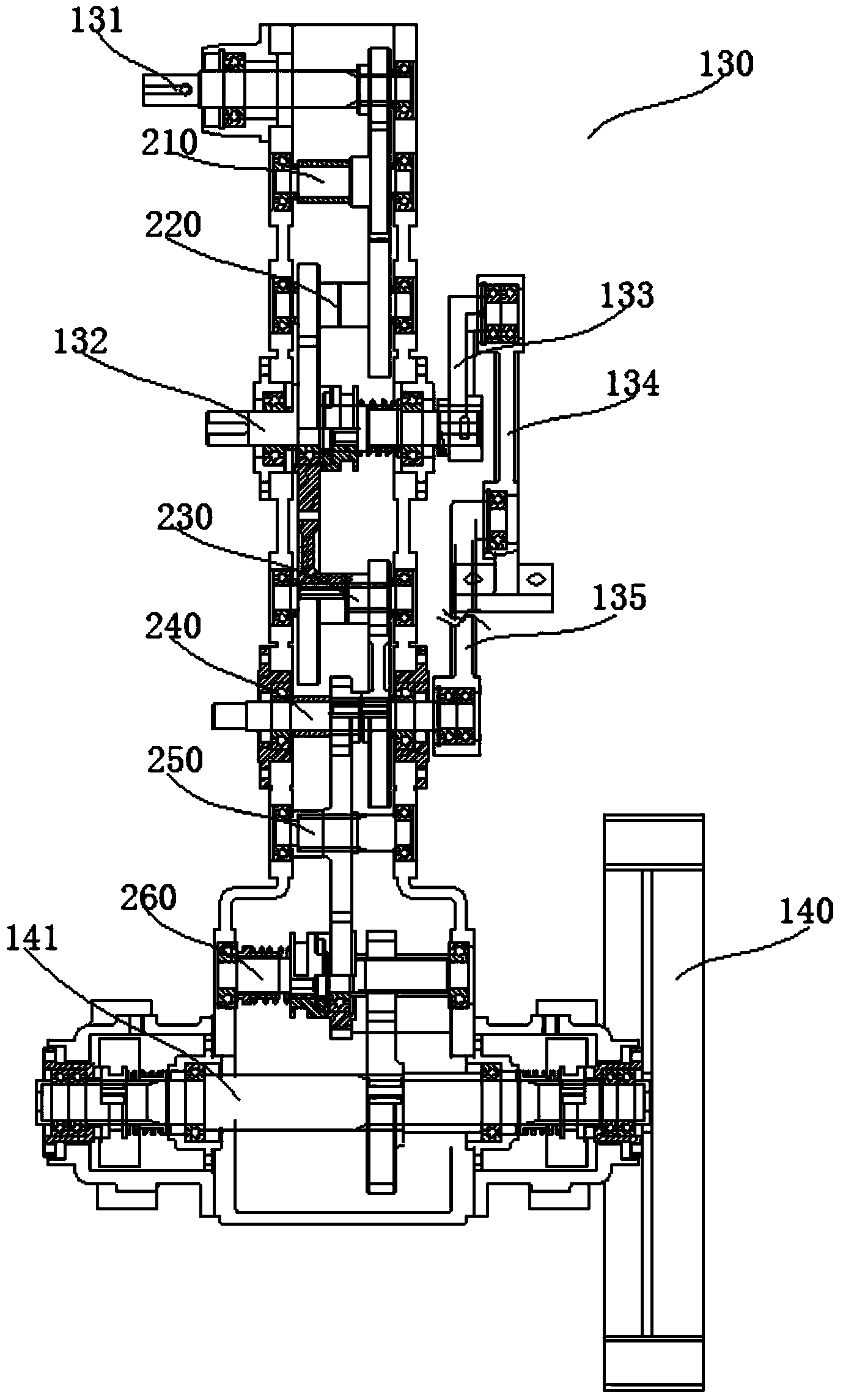
[0030] Such as figure 2 As shown, it is a gear box used in the tea planting machine in this embodiment, which is provided with an input shaft 131, a first transmission shaft 210, a second transmission shaft 220, a first output shaft 132, a third transmission shaft 230, and a fourth transmission shaft. The transmission shaft 240, the fifth transmission shaft 250, the sixth transmission shaft 260, and the second output shaft 141. The power mechanism 120 transmits power to the input shaft 131. The input shaft 131 sequentially transmits power to the first output shaft 132 via the first transmission shaft 210 and the second transmission shaft 220. The first output shaft 132 extends out of the gear box 130 and has both ends. The driving arm 133 is connected by a key; the first output shaft 132 sequentially transmits power to the second output shaft 141 via the third transmission shaft 230, the fourth transmission shaft 240, the fifth transmission shaft 250, and the sixth transmission shaft 260, and the fourth transmission shaft 240 extends out of the gear box 130 and both ends are connected to the connecting rod 135 through bearings. The second output shaft 141 extends out of the gear box 130 and both ends are provided with driving wheels 140. The second output shaft 141 drives the driving wheels 140.
[0031] Such as image 3 , Figure 4 Shown is the tiller tooth 136 used in the tea planting machine in this embodiment. It includes a first mounting part 310. The first mounting part 310 is configured with two curved teeth 320 in parallel. The machine body 100 is also provided with tiller teeth 136. The matched soil crushing rod 160 is located between the two curved teeth 320, and the working section of the matching soil crushing rod 160 and the tilling teeth 136 is level.
[0032] Such as Figure 5 , Image 6 As shown, the driving arm 133 used for the tea planting machine in this embodiment has a first shaft hole 510 at one end and a first mounting handle 520 at the other end. The first shaft hole 510 is keyed to the first output shaft 132, A screw hole 521 is provided in the first mounting handle 520 along the axial direction.
[0033] Such as Figure 7 , Picture 8 As shown, the connecting rod 135 used for the tea planting machine in this embodiment is configured with a second shaft hole 710 at one end and a second mounting handle 720 at the other end. The connecting rod 135 is rotatably arranged in the gear box through the second shaft hole 710 130 on.
[0034] Such as Picture 9 , Picture 10 As shown, the tilling arm 134 used for the tea planting machine in this embodiment is provided with a first mounting hole 910 which is matched with the first mounting handle 520 at one end, and a second mounting hole 910 which is matched with the second mounting handle 720 at the other end. Mounting hole 920. The tilling arm 134 is located at an end of the second mounting hole 920 and extends horizontally forward to form a second mounting part 930 which cooperates with the first mounting part 310 to fix the tilling teeth 136 on the tilling arm 134.
[0035] Such as Picture 11 As shown, this embodiment also provides a handle adjustment mechanism for the tea planting machine in this embodiment. The handle 110 in this embodiment is provided on the machine body 100 through the adjustment mechanism. The adjustment mechanism includes an adjustment plate 171 and a holder 172. One end of the adjusting plate 171 is fixedly connected to the handle 110, the other end of the adjusting plate 171 is configured as an arc-shaped end surface, and the arc-shaped end surface is provided with 7 slots; the holder 172 is constructed in a horseshoe shape, and the opening is provided with a holder 172 is fixed to the positioning hole 1110 on the machine body 100, and there is also a clamping rod 1120 that cooperates with the seven clamping slots.
[0036] The holder 172 is provided with a containing cavity 1130, the opening of the containing cavity 1130 is upward and the cross section is "convex"; the clamping lever 1120 is arranged on the containing cavity 1130 through the spring 1140, the clamping lever 1120 extends from the opening of the containing cavity 1130, the clamping lever A part of the bottom of 1120 located in the containing cavity 1130 extends to both sides to form a baffle. The joint action of the baffle and the spring 1140 enables the lever 1120 to be vertically telescopic in the containing cavity 1130. The holder 172 is also provided with a groove for the displacement of the clamping rod 1120, and both ends of the clamping rod 1120 extend outward to form an adjusting block 1150 extending from the groove.
[0037] In this embodiment, the power mechanism 120 is a gasoline engine, and the power output shaft 121 and the input shaft 131 of the power mechanism 120 transmit power through a pulley. The rotation speeds of the first output shaft 132 and the second output shaft 141 are the same. Both the second mounting portion 930 and the first mounting portion 310 are provided with screw holes, and the tilling teeth 136 are fixed to the tilling arm 134 through the cooperation of screws.
[0038] When the tea plantation machine of this embodiment is working normally, the power mechanism 120 transmits power to the input shaft 131 of the gear box 130 through the pulley. The gear box 130 is driven by the first output shaft 132 to drive the driving arm 133 to rotate, and the gear box 130 is driven by the second output shaft. 141 drives the driving wheel 140 to rotate. The driving wheel 140 and the guide wheel 150 cooperate to realize the walking of the tea garden tillage machine of this embodiment. Through the crank link mechanism constructed by the driving arm 133, the tilling arm 134 and the connecting rod 135, the tilling teeth are driven by the tilling arm 134. 136 Realize the plowing work of the tea garden tillage machine of this embodiment. The adjustment of the height of the handle 110 of the tea plantation machine in this embodiment is achieved by the adjustment of the clamping lever 1120 on the different channels of the adjustment disc 171.

PUM

no PUM

Description & Claims & Application Information

We can also present the details of the Description, Claims and Application information to help users get a comprehensive understanding of the technical details of the patent, such as background art, summary of invention, brief description of drawings, description of embodiments, and other original content. On the other hand, users can also determine the specific scope of protection of the technology through the list of claims; as well as understand the changes in the life cycle of the technology with the presentation of the patent timeline. Login to view more.

Similar technology patents

Classification and recommendation of technical efficacy words

  • Compact
  • Simple structure

Microlithographic projection exposure apparatus

InactiveUS20050068499A1Simple structureReliable and low-maintenance operationProjectorsPhotomechanical exposure apparatusCamera lensPhysics
Owner:CARL ZEISS SMT GMBH

People also interested in

Why Eureka
Try Eureka