Method for manufacturing composite material component

A technology of composite material components and prefabricated bodies, which is applied in the field of composite materials, can solve the problems of easy distortion and deformation of composite material components, low performance of chopped fibers, and easy brittle fracture, etc., so as to avoid product deformation, good impact resistance and good appearance good effect

Inactive Publication Date: 2015-02-25
CHENGDU AIRCRAFT INDUSTRY GROUP
View PDF0 Cites 11 Cited by
  • Summary
  • Abstract
  • Description
  • Claims
  • Application Information

AI Technical Summary

Problems solved by technology

For composite materials with a large ratio of length, width and thickness (the ratio of length, width and thickness is greater than or equal to 500:20:10), if continuous fibers are used, the manufactured composite components are easily distorted and deformed.
Therefore, products with large thickness and width are often manufactured, and finally processed to the required shape and size by CNC machining methods; but even so, the processed products are prone to bending, twisting and other deformations, and are uncontrollable
B. Composite materials made of chopped fibers can completely solve the problem of deformation of composite materials, but due to the low performance of chopped fibers, the chopped fiber-reinforced resin-based composite materials are relatively brittle during the manufacturing process, and brittle fractures are prone to occur during demoulding and other damage, unable to meet the performance requirements in the composite material manufacturing process

Method used


Image

  • Method for manufacturing composite material component
  • Method for manufacturing composite material component
  • Method for manufacturing composite material component

Examples


Embodiment Construction

[0031] The technical solution of the present invention will be further described in detail below in conjunction with the accompanying drawings, but the protection scope of the present invention is not limited to the following description.

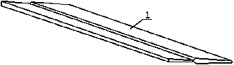
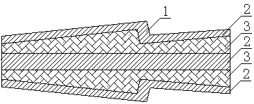
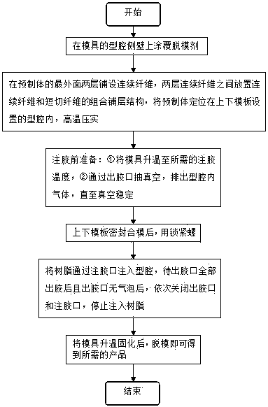
[0032] Such as image 3 As shown, a method for making composite material components is suitable for composite material components with a ratio of length, width, and thickness greater than or equal to 500:20:10. The composite material prefabricated components produced in this embodiment are as follows figure 1 As shown, its cross-section is in the shape of a step, with a length of 2160mm and a width of 70mm, and the thickness of the step area is 1.56-3.8mm. The member is geometrically asymmetrical in the length direction, and the member is also geometrically asymmetric in the width direction, showing a geometric form of thick at one end and thin at the other. . The method for making a composite material component depends on a mold for makin...


PUM


Abstract

The invention discloses a method for manufacturing a composite material component. The method comprises the following steps of S1: coating the side wall of a cavity of a die with a demolding agent; S2: paving a prefabricated body in the cavity: S21: paving continuous fibers on two layers on the outmost surface of the prefabricated body, and arranging a combined paved layer structure of the continuous fibers and chopped fibers between the two layers of the continuous fibers, and S22: positioning the prefabricated body in cavities formed in an upper die board and a lower die board, and performing high-temperature compaction; S3, sealing the upper die board and the lower die board for die assembling, locking the upper and lower die boards by a locking bolt; S41: heating the die to required glue injection temperature; S42: vacuuming through a glue outlet until the vacuum environment is stable; S5: injecting resin into the cavity, closing the glue outlet and a glue injection opening after the glue is completely discharged from the glue outlet, and stopping glue injection; and S6: heating and solidifying the die, and demolding to obtain a required product. The method has the beneficial effects that the composite material component meeting the requirement on the appearance is manufactured, so that the product is unlikely to deform, and the processing cost can be effectively lowered.

Description

technical field [0001] The invention relates to the field of composite materials, in particular to a method for making composite material components. Background technique [0002] With the continuous development of aerospace technology, aerospace vehicles are also facing huge cost pressures, and weight is the most important source of cost in aerospace. With the development of advanced composite materials technology, the amount of composite materials is increasing continuously. Composite materials are lighter than aluminum alloys and are widely used in the aerospace field. [0003] A large number of narrow and variable cross-section composite members (the ratio of length, width and thickness is greater than or equal to 500:20:10) are used in the aerospace field, which mainly play the role of dimension shape and are non-load-bearing structural components. At present, such narrow and variable cross-section composite members can be formed by aluminum alloy numerical control pro...

Claims


Application Information

Patent Timeline
Patent Type & Authority Applications(China)
IPC IPC(8): B29C70/36
CPCB29C70/36
Inventor 闫超刘志杰徐伟伟罗辑冷卫红
Owner CHENGDU AIRCRAFT INDUSTRY GROUP
Why Eureka
Try Eureka