Vacuum tube solar heat collector

A technology of solar heat collectors and vacuum tubes, applied in the direction of solar heat collectors, solar heat collectors using working fluids, solar thermal energy, etc., can solve the problem of inability to further improve the heat exchange efficiency of solar heat collectors Increased resistance, large space occupation, etc., achieve the effect of reducing weight, saving installation area, and increasing surface area

Inactive Publication Date: 2015-02-25
白峻光 +3
View PDF6 Cites 7 Cited by
  • Summary
  • Abstract
  • Description
  • Claims
  • Application Information

AI Technical Summary

Problems solved by technology

[0002] The existing solar collectors have the characteristics of freezing resistance, fast start-up, no fouling, good heat preservation, high pressure bearing, good thermal shock resistance, easy installation and reliable operation, and have been well received by users. The technology is relatively mature, and it is sought after by people as a source of clean and cheap heat energy. However, in large and medium-sized cities, the promotion of solar collectors has encountered a bottleneck. The reason is that when used in cities, solar collectors The array occupies a large space, and in order to obtain sufficient solar radiation, it needs to be placed on the roof of the building, so under the constraints of the limited area of ​​the roof, only some residents can enjoy the heat source provided by the solar collector. The heat collection in the vacuum tube of the solar collector belongs to the environmental heat collection. The temperature in the vacuum tube can reach more than 200 degrees, while the temperature of normal water does not exceed 100 degrees

Method used


Image

  • Vacuum tube solar heat collector
  • Vacuum tube solar heat collector

Examples


Embodiment Construction

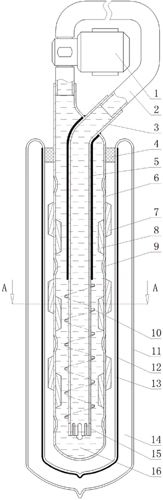
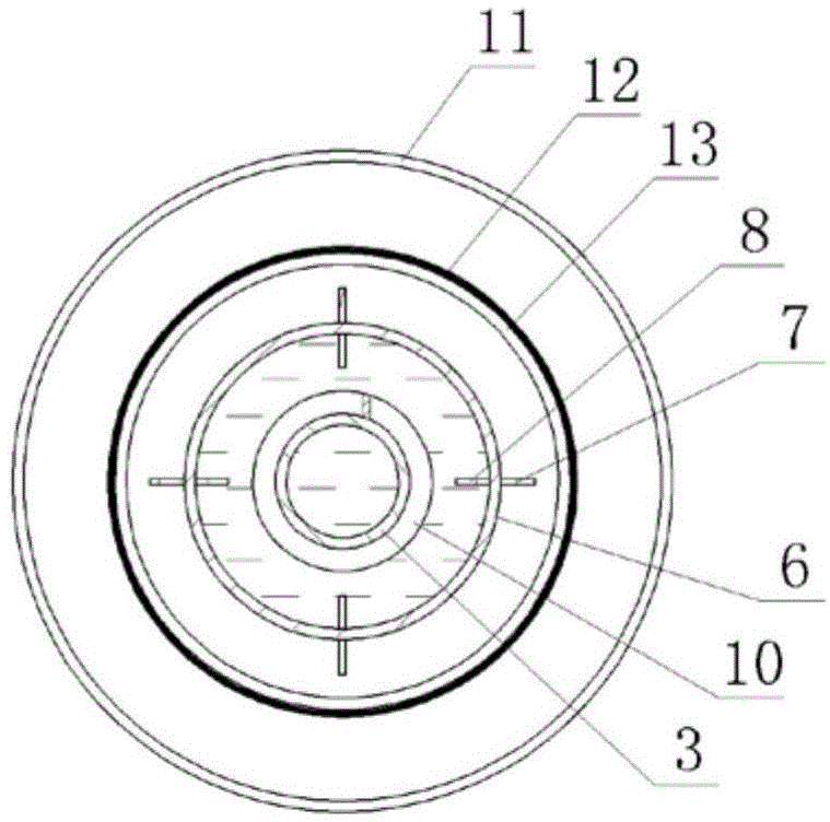
[0016] A vacuum tube solar heat collector, which has a vacuum tube and a heat exchange tube 2, a circulating water pump 1 is installed on the heat exchange tube, and a heat collection tube is installed inside the vacuum tube. The lower end of the tube is a blind end, the upper end of the outer copper tube communicates with one end of the heat exchange tube, a rubber sleeve 4 for sealing is installed between the outer copper tube and the vacuum tube, the inner copper tube is placed in the outer copper tube, and the inner copper tube There is a gap between the lower end of the copper tube and the blind end of the outer copper tube, and the upper end of the inner copper tube passes through the tube wall of the outer copper tube to communicate with the other end of the heat exchange tube. The inner copper tube, the outer copper tube and the heat exchange tube The superconducting liquid 16 is housed in it.

[0017] The vacuum tube is composed of inner and outer glass blind tubes 11...


PUM


Abstract

A vacuum tube solar heat collector is provided with a vacuum tube and a heat exchange tube, a circulating water pump is installed on a pipeline of the heat exchange tube, a heat collecting tube is installed on the inner side of the vacuum tube and is provided with an outer copper tube and an inner copper tube, the lower end of the outer copper tube is the blind end, the upper end of the outer copper tube is communicated with one end of the heat exchange tube, a rubber sleeve used for sealing is arranged between the outer copper tube and the vacuum tube, the inner copper tube is arranged in the outer copper tube, a gap is formed between the lower end of the inner copper tube and the blind end of the outer copper tube, the upper end of the inner copper tube penetrates through the wall of the outer copper tube and is communicated with the other end of the heat exchange tube, and superconduction liquid is contained in the inner copper tube, the outer copper tube and the heat exchange tube. The vacuum tube solar heat collector has the advantages that the heat exchange efficiency is high, the size is small, the installing area is saved, and the weight and the manufacturing cost of the heat collector are reduced.

Description

technical field [0001] The invention relates to a solar heat collector, in particular to a vacuum tube solar heat collector. Background technique [0002] The existing solar collectors have the characteristics of freezing resistance, fast start-up, no fouling, good heat preservation, high pressure bearing, good thermal shock resistance, easy installation and reliable operation, and have been well received by users. The technology is relatively mature, and it is sought after by people as a source of clean and cheap heat energy. However, in large and medium-sized cities, the promotion of solar collectors has encountered a bottleneck. The reason is that when used in cities, solar collectors The array occupies a large space, and in order to obtain sufficient solar radiation, it needs to be placed on the roof of the building, so under the constraints of the limited area of ​​the roof, only some residents can enjoy the heat source provided by the solar collector. The heat collect...

Claims


Application Information

Patent Timeline
IPC IPC(8): F24J2/26F24J2/46F24S10/40F24S10/75
CPCF24S10/40Y02E10/44
Inventor 白峻光白岩松白凇会刘艳萍
Owner 白峻光
Why Eureka
Try Eureka