Strengthened evaporation heat transferring tube

A heat transfer tube and tube body technology, applied in the field of heat transfer tubes, can solve problems such as irregular and inconsistent bending shapes, cavity shapes, inconsistent sizes, and decline in evaporation heat transfer performance, and achieve uniform structural shapes and bubble formation Consistent with the growth process, the effect of stabilizing the evaporation performance

Inactive Publication Date: 2015-02-25
GOLDEN DRAGON PRECISE COPPER TUBE GROUP
View PDF11 Cites 11 Cited by
  • Summary
  • Abstract
  • Description
  • Claims
  • Application Information

AI Technical Summary

Problems solved by technology

However, the processing process of the T-shaped fins is to press the vertical fins through the hobbing knife to form a flat top of the fins, so that the vertical fins ( figure 1 Medium 2) It may be bent,...

Method used


Image

  • Strengthened evaporation heat transferring tube
  • Strengthened evaporation heat transferring tube
  • Strengthened evaporation heat transferring tube

Examples


Embodiment 1

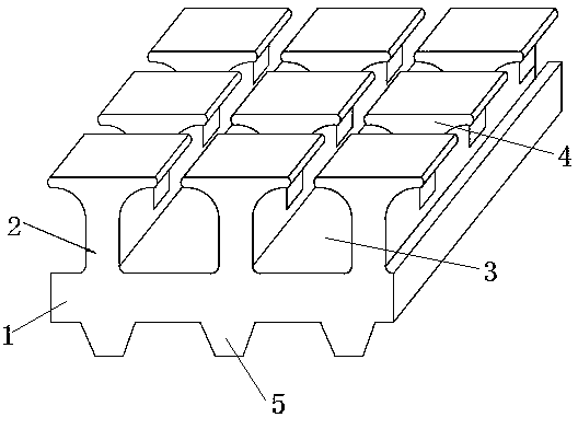
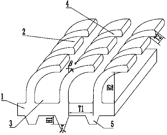
[0018] Such as figure 2 As shown, the enhanced evaporation heat transfer tube of the present invention includes an integrally formed tube body 1 and fins 2, and the fins 2 are coiled on the outer circumferential surface of the tube body 1 in a helical direction; the fins 2 are formed by cutting tools In order to uniformly bend and incline toward the axial direction of the tube body 1, the gap between the fins 2 and the tube body 1 forms a cavity 3 for evaporation; the fins 2 are provided with a plurality of fins along the circumferential direction of the tube body 1. Grooves 4, said finned grooves 4 divide the cavity 3 into a plurality of small holes.

[0019] The fins 2 are provided with 50 fins 2 per inch along the axial direction of the tube body 1, the helix angle is 1°, the height H2 of the small holes is 0.4 mm, and the number of fin grooves 4 is 150. The circumference of the small holes is The pitch T2 is 0.1mm; the inclination angle β of the fins is 45°.

[0020] Th...

Embodiment 2

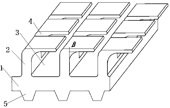
[0022] Such as image 3 As shown, the enhanced evaporation heat transfer tube of this embodiment has the same basic structure and principle as that of Embodiment 1, except that the inclination angle β of the fins is 90°. Compared with the existing heat transfer tube that directly presses the fins with a calender knife, the vertical part of the fins will not be deformed, and the shape of the holes is regular.

[0023] In the enhanced evaporation heat transfer tube of the present invention, many cavities formed by the gaps of the fins provide the vaporization core when the refrigerant evaporates, thereby strengthening the evaporation heat transfer; the ring-shaped passage formed by the cavities connected along the spiral is beneficial to the cooling of the refrigerant. The circular flow enhances the disturbance of the vapor-liquid phase when the refrigerant evaporates, thereby enhancing the heat exchange effect; the spiral fins on the circumference are divided into multiple smal...


PUM

PropertyMeasurementUnit
Heightaaaaaaaaaa
Heightaaaaaaaaaa
Tube wall thicknessaaaaaaaaaa

Abstract

The invention provides a strengthened evaporation heat transferring tube comprising a tube body and fins, the tube body and the fins are integrally formed, the fins are wound around the surface of the outer circumference of the tube body in the spiral direction, the fins are uniformly bent and inclined in the axial direction of the tube body through a tool, gaps between the fins and the tube body form evaporation cavities, a plurality of fin grooves are formed in the fins in the circumferential direction of the tube body, and the fin grooves divide the cavities into multiple small holes. According to the strengthened evaporation heat transferring tube, the fins are uniformly bent and inclined through the tool and will not twist or deform, and the structural shapes of the cavities are uniform, so that bubbles are uniform in the formation and growth processes, the evaporation performance of the heat transferring tube is stabilized, and the heat exchange efficiency of the heat transferring tube is improved.

Description

technical field [0001] The invention relates to a heat transfer tube, in particular to an enhanced evaporation heat transfer tube. Background technique [0002] With the development of enhanced heat transfer technology, surface porous tubes are now well known and applied by various air-conditioning companies. The cavities processed on the outer surface can become the place for the refrigerant to form bubbles. The shape and size of the cavities have a direct impact on maintaining the generation of bubbles and the growth of bubbles. For the convenience of processing, the shape of the outer fins is often processed into a T shape. For example, patent CN200510134630.9 "A kind of flooded copper evaporation heat exchange tube for electric refrigeration" and patent CN200910135786.7 "evaporator heat transfer tube" are all T-shaped fins (such as figure 1 ), forming holes for evaporative heat exchange between the fins. The heat exchange tubes used in the falling film evaporator CN10...

Claims


Application Information

Patent Timeline
IPC IPC(8): F28F1/42F25B39/02
Inventor 武永强王志军李彭李前方王大同杨振堃袁贵业
Owner GOLDEN DRAGON PRECISE COPPER TUBE GROUP
Why Eureka
Try Eureka