Radio frequency positioning method, device and system

A technology of positioning device and positioning method, which is applied in the direction of measuring device, radio wave measuring system, utilizing re-radiation, etc., can solve the problems that it is difficult to determine the azimuth angle and height, can only be used in indoor environment, and determine portable equipment or targets, etc. To achieve the effect of a wide range of application prospects

Inactive Publication Date: 2015-02-25
江苏舟航物联网技术有限公司
View PDF9 Cites 37 Cited by
  • Summary
  • Abstract
  • Description
  • Claims
  • Application Information

AI Technical Summary

Problems solved by technology

The Chinese patent application with publication number CN103728645A proposes an indoor and outdoor positioning system and its positioning method. Due to the influence of the position of the signal receiving antenna and the diffraction of electromagnetic waves, it is difficult to rely on the receiving and positioning equipment to determine the azimuth of the portable device or the target. Calculate the distance between the target and the receiving device based on the signal strength
The Chinese patent application with publication number CN103679087A proposes a positioning method based on radio frequency technology, which relies on adjusting the recognition range of the card reader to determine the approximate range of the tag, but it is difficult to determine its azimuth, angle and height
The Localizers indoor positioning system developed by AWTHER WIRE & LOCATION of the United States uses at least three reference points, and monitors the pseudo-random signals carried in the signal through the pulse communication between the ultra-wideband receiver with positioning and several reference positioning transceivers. Code time delay to judge the distance to different reference points, and then determine the three-dimensional coordinates of unknown points, but this solution is expensive and can only be used in indoor environments, and cannot realize portable measurement in outdoor environments or complex environments
The Chinese patent application with the publication number CN101770009A proposes a radio frequency positioning technology. In the measurement process, a reference signal source or a reference electronic tag needs to be added, and the relative distance between the reader and the reference signal source needs to be determined to realize the estimation of the target distance. , which increases the difficulty of measurement, and cannot realize the measurement of three-dimensional space distance
The Chinese patent application with the publication number CN101300504A discloses a radio frequency positioning system, which mainly relies on multiple locators to measure the position. This method is not only expensive, but also can only measure the plane position, and cannot determine its height range.
The Chinese patent application with the publication number CN101672907A estimates the distance to the radio frequency positioning system based on the antenna size of the minimum power radio frequency signal received in the antenna group, which also cannot realize the three-dimensional positioning of the target
[0004] Comprehensive research found that although relative distance measurement can be achieved with the help of radio frequency identification technology, the measured information is limited to plane distance or relative distance, and it is difficult to obtain the geographical coordinates (including longitude, latitude and altitude) of the measured target or relative to the reader. The azimuth angle, pitch angle and height information, can not obtain accurate three-dimensional space geographic coordinate information
Therefore, the existing positioning technology, whether it is wireless local area network positioning or radio frequency identification tag positioning system, can only achieve approximate ranging and positioning on a two-dimensional plane, and cannot achieve low-cost outdoor or complex environment three-dimensional coordinate positioning

Method used


Image

  • Radio frequency positioning method, device and system
  • Radio frequency positioning method, device and system
  • Radio frequency positioning method, device and system

Examples


Embodiment 1

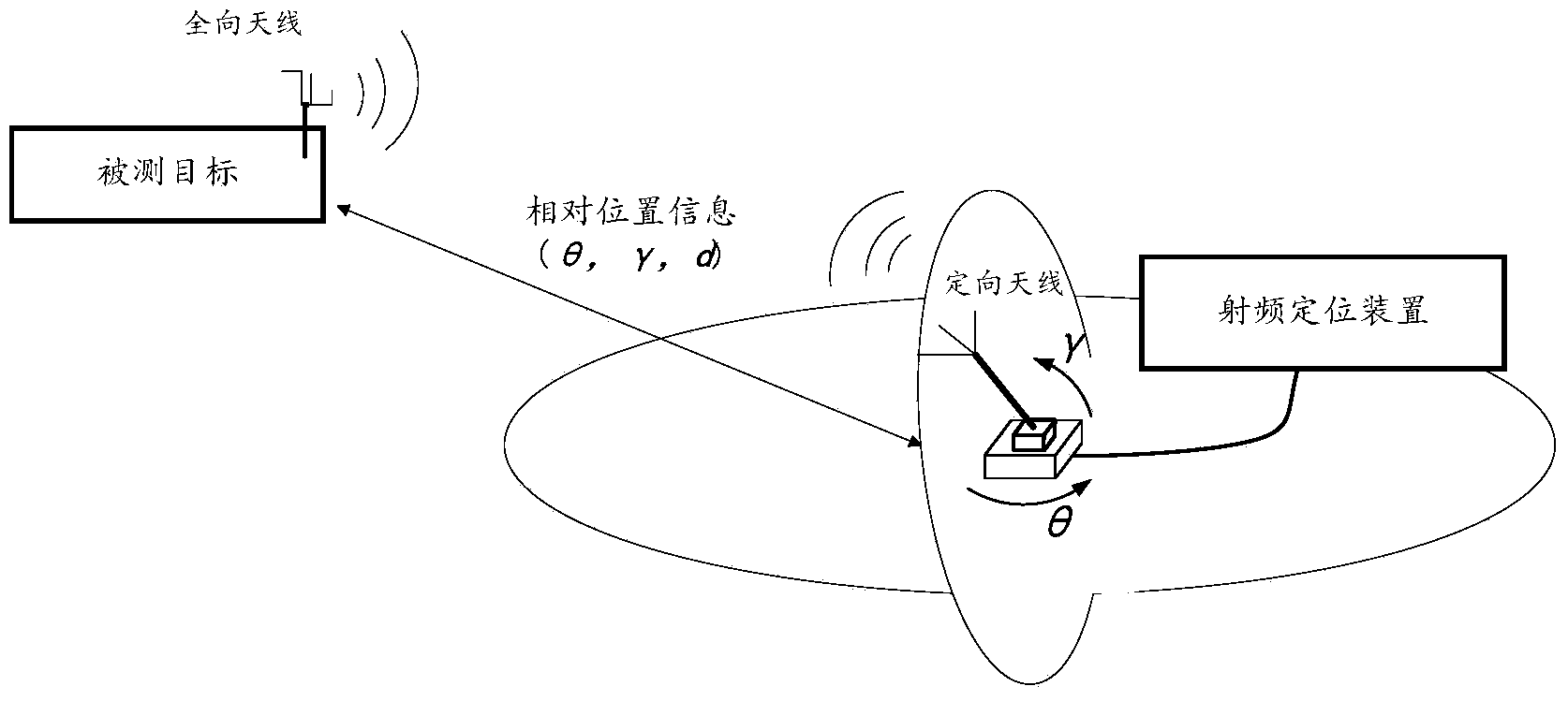
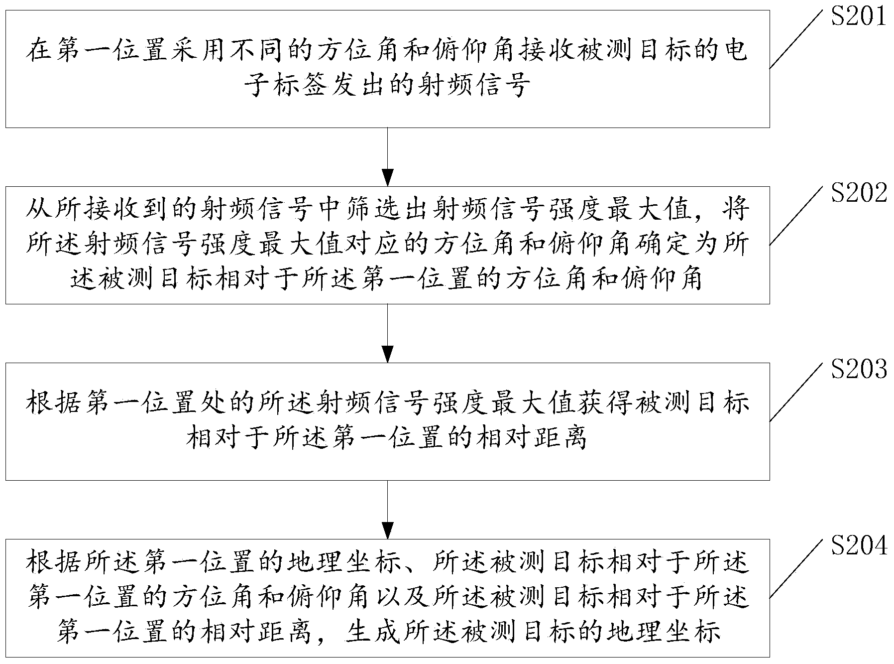
[0024] This embodiment provides a radio frequency positioning method, which can realize all-round radio frequency positioning of a measured target in a three-dimensional space. This method uses the directional antenna of the radio frequency positioning device to scan the three-dimensional space at various azimuths and elevation angles to search for the radio frequency signal sent by the electronic tag of the target to be measured, and obtain the measured signal according to the strength and direction of the received radio frequency signal. The relative distance between the target and the measurement location and the direction relative to the measurement location, so as to determine the geographical coordinates (longitude, latitude and altitude) of the measured target.

[0025] figure 1 It is an application scenario diagram of this embodiment, and the method of this embodiment will be described in detail below with reference to this diagram. Such as figure 1 As shown, in this...

Embodiment 2

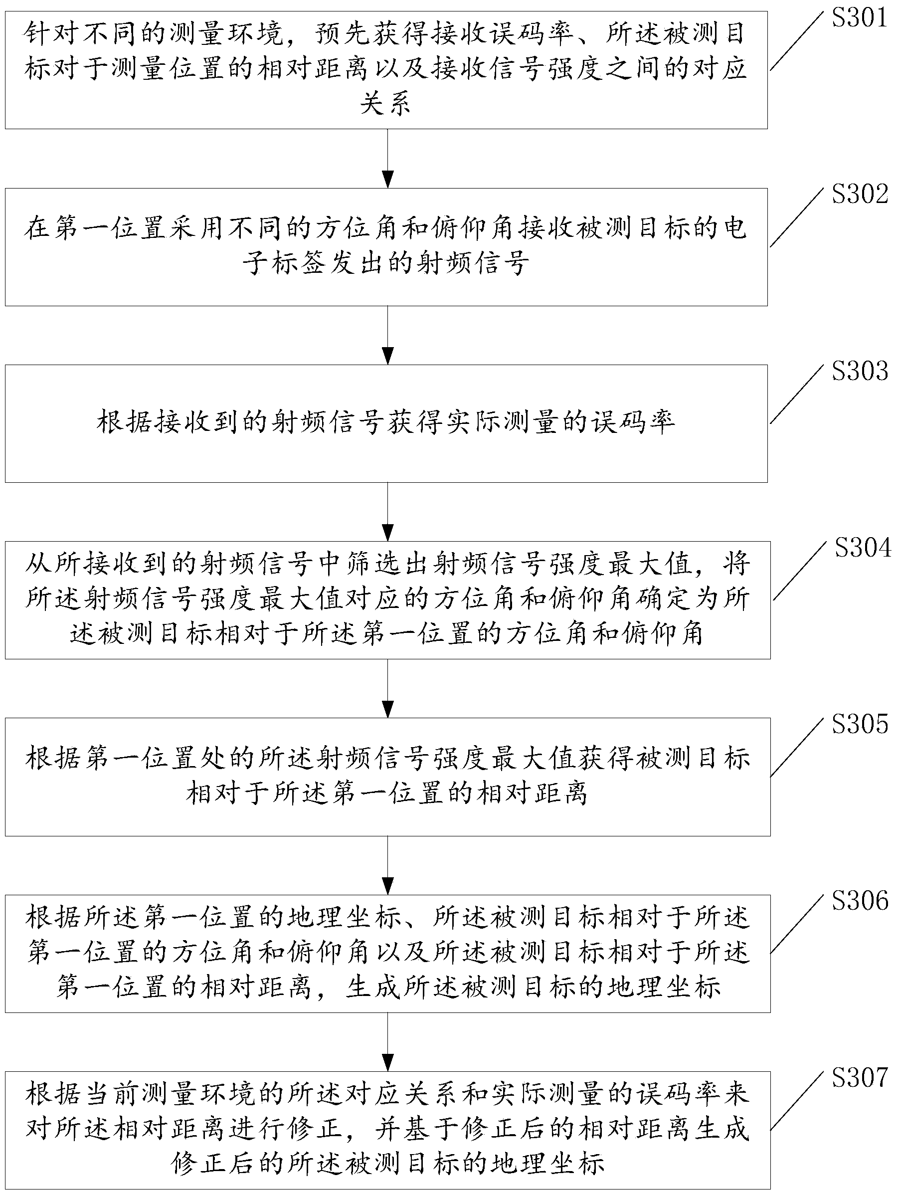
[0041] This embodiment is based on Embodiment 1, and includes not only the actual measurement phase of Embodiment 1, but also the calibration phase before the actual measurement phase, and the process of correcting the measurement results of Embodiment 1. Considering the impact of different measurement environments on the bit error rate, the specific calibration process needs to be carried out according to various measurement environments. This calibration stage is mainly used to measure the bit error rate of different measurement distances in different measurement environments. The relative distance between the measured object and the measurement location measured in a certain measurement environment needs to be corrected by using the calibration data obtained in the calibration stage, and then the geographic coordinates of the measured object are corrected.

[0042] image 3 It is the flowchart of this embodiment. Such as image 3 As shown, the method includes:

[0043] S...

Embodiment 3

[0081] The difference between this embodiment and Embodiment 2 is that in the calibration stage, it is not only necessary to establish the relationship between the received bit error rate, the relative distance of the measured target to the measurement location, and the received signal strength for different measurement environments as illustrated in Embodiment 2. In addition, it is necessary to obtain the measurement deviations of azimuth and elevation angles in different measurement environments during the calibration stage, and use the pre-acquired measurement deviations of azimuth and elevation angles to correct the actual measured azimuth and elevation angles, thereby correcting The geographic coordinates of the measured object.

[0082] Figure 4 It is a detailed flowchart of this embodiment.

[0083] S401: According to different measurement environments, obtain the measurement deviation of pitch angle and azimuth angle in advance;

[0084] Specifically, since measurem...


PUM


Abstract

The invention provides a radio frequency positioning method, device and system. The radio frequency positioning method comprises the following steps that radio-frequency signals sent out by an electronic tag of a detected object are received at different azimuth angles and pitch angles in a first position; the radio-frequency signal with the maximum intensity value is screened out from the received radio-frequency signals, and the azimuth angle and the pitch angle which correspond to the radio-frequency signal with the maximum intensity value are determined as the azimuth angle and the pitch angle, relative to the first position, of the detected object; the relative distance, relative to the first position, of the detected object is obtained according to the radio-frequency signal with the maximum intensity value at the first position; according to the geographical coordinates of the first position, the azimuth angle and the pitch angle, relative to the first position, of the detected object, and the relative distance, relative to the first position, of the detected object, the geographical coordinates of the detected object are generated.

Description

technical field [0001] The present invention relates to the field of electromechanical testing devices and instruments, in particular to a radio frequency positioning method, device and system, and more specifically, to a method, device and system for omnidirectional and long-distance radio frequency positioning of space targets. Background technique [0002] In a specific environment, it is difficult to achieve three-dimensional space positioning of long-distance targets by relying on existing positioning methods and means. For example: Although GPS and base station positioning have the characteristics of large coverage and good versatility, they are easily affected by the environment and cannot achieve high-precision positioning in closed spaces without GPS or base station signals (such as underground parking lots, mines or warehouses). Low-cost positioning; Infrared indoor positioning is only suitable for short-distance transmission, and is easily affected by fluorescent ...

Claims


Application Information

Patent Timeline
Patent Type & Authority Applications(China)
IPC IPC(8): G01S11/06
CPCG01S11/06
Inventor 戚源黄毓魏文娟刘苗苗
Owner 江苏舟航物联网技术有限公司
Why Eureka
Try Eureka