Novel motor rotor structure

A motor rotor, a new type of technology, applied in the direction of magnetic circuit shape/style/structure, magnetic circuit rotating parts, etc., can solve the problems of increasing assembly difficulty and process, wasting materials, reducing assembly efficiency, etc., to save motor space and improve Assembly efficiency, material cost saving effects

Inactive Publication Date: 2015-02-25
ANHUI JEE AUTOMATION EQUIP CO LTD
5 Cites 0 Cited by

AI-Extracted Technical Summary

Problems solved by technology

[0004] The traditional drive motor currently on the market has a baffle at the end of the rotor, and the baffle is installed on the rotor bracket through bolts to block the magnetic steel and the punching plate. It is bulky and has the following obvious defects: 1) Waste of space, For the compact drive assembly of the whole vehicle, the baffle increases the ...

Method used

In summary, the punching sheet 20 cooperates with the rotor bracket 30 through the keyway 31, the magnetic steel 10 is pressed into the punching sheet 20 by excessive fit, and the two ends of the magnetic steel 10 are poured into the injection plastic 40, so that the magnetic steel 10 and the punching Sheet 20 is further fixed. The core of the present invention is that there are no rotor baffles at b...

Abstract

The invention relates to a novel motor rotor structure comprising a punching sheet with the circular shape, and the inner circumference of the punching sheet is provided with positioning keys. The outer circumference of a rotor frame is provided with positioning key grooves matching with the positioning keys, and the punching sheet and the outer circumference of the rotor frame are in fit clearance; a plurality of inserting grooves allowing a magnetic steel to insert are arranged on the circumference of the punching sheet, the magnetic steel and the punching sheet are in fit clearance, and plastic rubber is injected in the clearance between two ends of the magnetic steel and the punching sheet. Since the punching sheet and the rotor frame are in fit clearance, the punching sheet and the rotor frame can be fixed tightly while the punching sheet is free of being pressed by a baffle; the magnetic steel and the punching sheet are in fit clearance, the plastic rubber is injected in the clearance between the magnetic steel and the punching sheet to fix the magnetic steel, the ends of the magnetic sheets are free of being shielded by the baffle, the magnetic steel can be applied to the motor rotor assembly directly, the occupied space is small, the rotor structure is simple, the space of the motor is saved effectively, material cost is saved, and the assembling efficiency of the rotor is improved.

Application Domain

Magnetic circuit rotating parts

Technology Topic

EngineeringPunching

Image

  • Novel motor rotor structure
  • Novel motor rotor structure
  • Novel motor rotor structure

Examples

  • Experimental program(1)

Example Embodiment

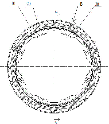
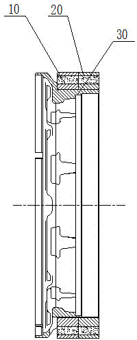
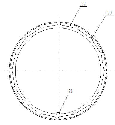
[0019] A new type of motor rotor structure includes a ring-shaped punching piece 20, a positioning key 21 is arranged on the inner circle, and a key groove 31 matching the positioning key 21 is provided on the outer ring of the rotor support 30. The punching piece 20 and the rotor The outer ring of the bracket 30 has an interference fit. The punching piece 20 has a plurality of slots 22 for inserting the magnet 10 along its circumference. The magnet 10 and the punching piece 20 are interference fit, and the magnets 10 at both ends of the magnet 10 Fill the gap between the slot 22 and the punching piece 20 with injection molding glue 40, such as figure 1 , 2 , 5 shown.
[0020] Such as figure 1 , 4 As shown, the outer ring of the rotor bracket 30 is a ring-shaped retaining wall 32 arranged on the rotor bracket 30, and the inner circular surface of the punching piece 20 is closely attached to the outer circular surface of the ring-shaped retaining wall 32, and is arranged in The positioning key 21 on the inner circle of the punching piece 20 is matched with the key groove 31 opened on the annular retaining wall 32. Such as image 3 As shown, the slots 22 are equally spaced along the circumference of the punching sheet 20, and the cross-sectional shape of the slots 22 is roughly a rectangle with a narrow top and a wide bottom. The length of the slots 22 is greater than the length of the magnet 10, and the slots 22 The depth of the groove is the same as the width of the magnet 10, the height of the slot 22 is the same as the height of the magnet 10, and the cross section of the magnet 10 is rectangular.
[0021] During the assembly process of the motor rotor, the punching piece 20 is pressed into the outer ring of the rotor support 30 through a press, the punching piece 20 and the rotor support 30 are interference fit, and the key is connected and positioned; then the magnet 10 is pressed into the punching piece 20 by the press In the slot 22; finally, the injection molding glue 40 is poured into the gap between the punch 20 and the magnetic steel 10 through the tooling.
[0022] To sum up, the punching piece 20 is matched with the rotor support 30 through the keyway 31, the magnet 10 is pressed into the punching piece 20 through over-fitting, and the two ends of the magnet 10 are filled with injection molding glue 40, so that the magnet 10 and the punching piece 20 are further fixed. The core of the present invention is that there is no rotor baffle at both ends of the motor rotor. By increasing the lamination coefficient of the punching piece 20, and fixing the magnet 10 and the punching piece 20 by the injection molding glue 40, the rotor structure is more compact, lighter, and space saving. , Reduce the difficulty of assembly, but also prevent the punching piece 20 and the magnetic steel 10 from falling off.

PUM

no PUM

Description & Claims & Application Information

We can also present the details of the Description, Claims and Application information to help users get a comprehensive understanding of the technical details of the patent, such as background art, summary of invention, brief description of drawings, description of embodiments, and other original content. On the other hand, users can also determine the specific scope of protection of the technology through the list of claims; as well as understand the changes in the life cycle of the technology with the presentation of the patent timeline. Login to view more.

Similar technology patents

Automatic box making device and method

ActiveCN105235278AImprove processing speed and productivitysmall footprint
Owner:中科天工(广东)智能技术有限公司

Rolling piston type compressor with no reservoir

Owner:SHANGHAI HITACHI ELECTRICAL APPLIANCES CO LTD

Multistage integrated hydrodynamic cyclone separator

InactiveCN102512857ASmall footprintEasy to install and control
Owner:BEIJING UNIVERSITY OF CIVIL ENGINEERING AND ARCHITECTURE

Automatic processing production line for metal sheets

ActiveCN105458718ASmall footprintReasonable production beat matching
Owner:江苏扬力数控机床有限公司

Classification and recommendation of technical efficacy words

  • Simple structure
  • small footprint

Sharing system for air-conditioning coat

InactiveCN107440179ASimple structureeasy to wear
Owner:QINGDAO HAIER AIR CONDITIONER GENERAL CORP LTD

Feeding device of sorter of batteries plate

InactiveCN101357717ASimple structurecooperate well
Owner:NANJING NORMAL UNIVERSITY

Emergency parachuting device and method for multiple-rotor unmanned aerial vehicle

InactiveCN103895870Aavoid aircraft crashSimple structure
Owner:SOUTH CHINA AGRI UNIV +1
Why Eureka
Try Eureka