
Power supply unit with micro-pulse wave absorption function

A technology of micropulse wave and power supply device, which is applied in the field of signal transmission, can solve the problems of not considering the existence, the blank of understanding and processing, and the decline of AC ripple suppression ability of the power supply, so as to achieve the improvement of resolution, soft tone, and improvement of transient and Effect of EMC performance

Active Publication Date: 2017-09-15
颜至远
View PDF9 Cites 0 Cited by
  • Summary
  • Abstract
  • Description
  • Claims
  • Application Information

AI Technical Summary

Problems solved by technology

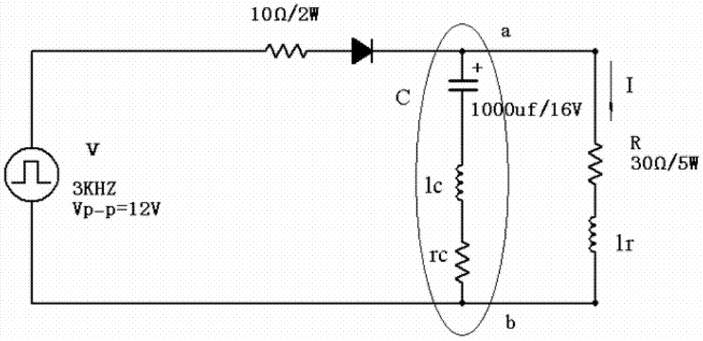
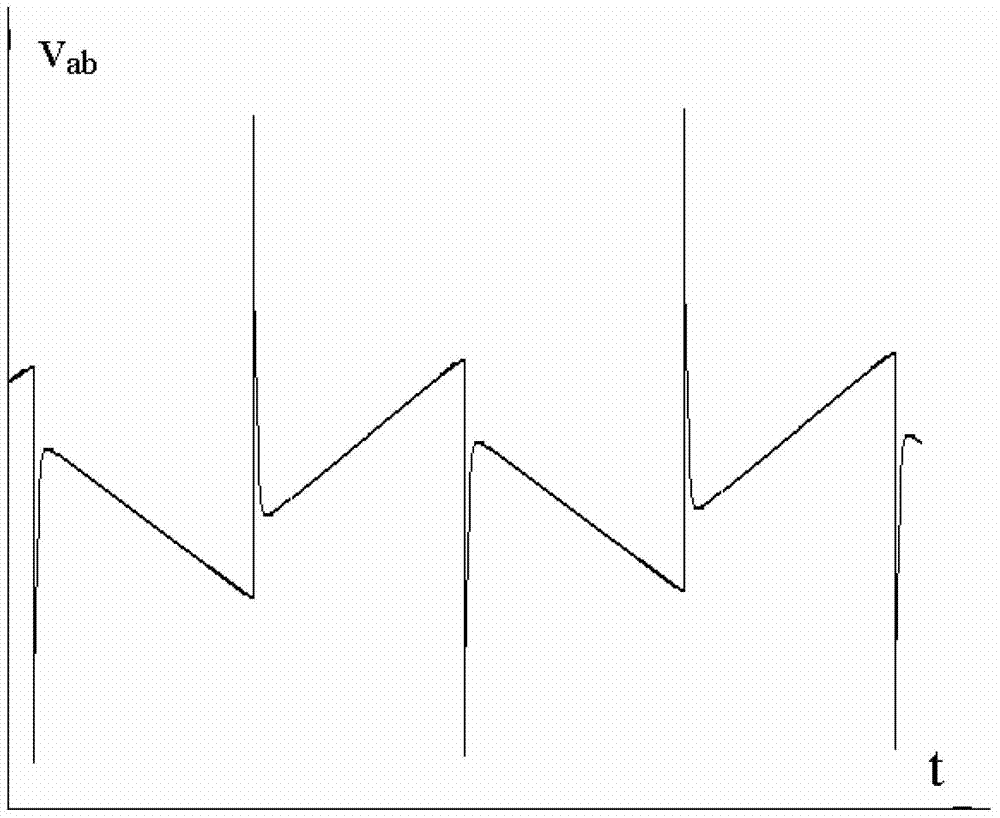
[0003] The spectrum analysis method based on Fourier transform is easy to ignore this kind of pulse wave which may not appear frequently but has extremely high-frequency properties locally, because it is difficult for traditional instruments to capture it in nanoseconds and picoseconds. area, so the usual power supply ripple evaluation system does not consider its existence in this area at all.
In fact, the ability of the conventional circuit to suppress the AC ripple of the power supply gradually decreases with the increase of the frequency, so it is necessary to pay enough attention to its harm.
[0004] At present, in the field of high-frequency circuits and audio which are extremely sensitive to such pulse waves, the understanding and treatment of this problem is even more blank.

Method used


Image

  • Power supply unit with micro-pulse wave absorption function
  • Power supply unit with micro-pulse wave absorption function
  • Power supply unit with micro-pulse wave absorption function

Examples


Embodiment Construction

[0021] Embodiments of the present invention are described in detail below, examples of which are shown in the drawings, wherein the same or similar reference numerals designate the same or similar elements or elements having the same or similar functions throughout. The embodiments described below by referring to the figures are exemplary only for explaining the present invention and should not be construed as limiting the present invention.

[0022] The following disclosure provides many different embodiments or examples for implementing different structures of the present invention. To simplify the disclosure of the present invention, components and arrangements of specific examples are described below. Of course, they are only examples and are not intended to limit the invention. Furthermore, the present invention may repeat reference numerals and / or letters in different instances. This repetition is for the purpose of simplicity and clarity and does not in itself indicat...


PUM


Abstract

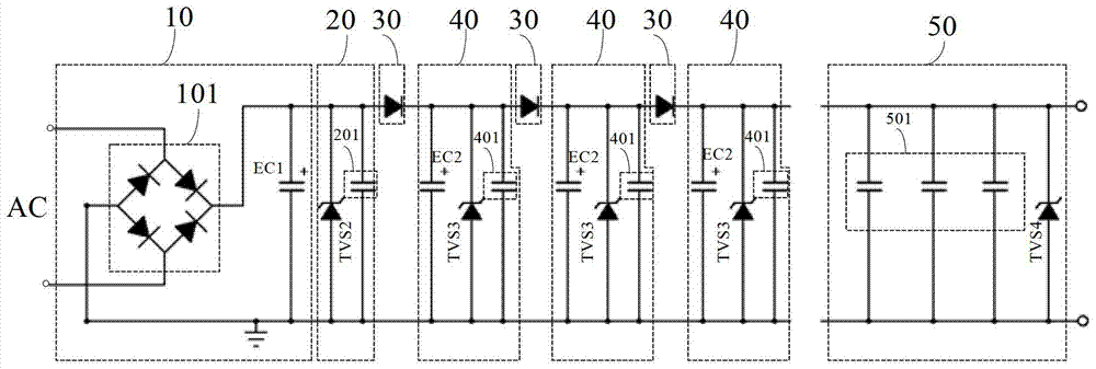
The invention discloses a power device with a micropulse wave absorption function. The power device comprises a rectification and filter module, a first micropulse wave discharge module, at least one micropulse wave insulation module, at least one second filter module and a second micropulse wave discharge module. The rectification and filter module comprises a rectifier bridge and a first filter capacitor. The first micropulse wave discharge module is arranged at the output end of the rectifier bridge and used for discharging micropulse waves generated by the first filter capacitor. The micropulse wave insulation modules are sequentially arranged at the output end of the rectifier bridge and used for insulating out negative micropulse waves generated by a pin inductor of the first filter capacitor, and each second filter module comprises a second filter capacitor. The second micropulse wave discharge module is arranged at the output end of the power device and used for carrying out secondary discharging on residual micropulse waves passing through the at least one micropulse wave insulation module and micropulse waves generated by the second filter capacitors. According to the power device, micropulse waves with time intervals shorter than a nanosecond section and a microsecond section can be absorbed, the transient performance and EMC performance of a power source in a high-frequency circuit system are effectively improved.

Description

technical field [0001] The invention relates to the technical field of signal transmission, in particular to a power supply device with a micro-pulse wave absorption function. Background technique [0002] In a common AC-DC power supply circuit, due to the additional parameters such as inductance, high-frequency skin resistance, and DC resistance at the pin of the filter capacitor, when the load current changes suddenly, or the source current changes suddenly when driving an inductive load, A pulse wave will appear in the voltage across the filter capacitor. Due to various reasons such as conductor skin effect, conductor surface defects, absorbing device speed, etc., the pulse wave cannot be absorbed by various conventional devices including line-to-line capacitance in the very short time (such as picosecond and femtosecond intervals) when it first occurs. The device absorbs well, which is a typical EMI (ElectroMagnetic Interference, electromagnetic interference) problem th...

Claims


Application Information

Patent Timeline
Patent Type & Authority Patents(China)
IPC IPC(8): H02M1/44
CPCH02M1/44
Inventor 颜至远
Owner 颜至远
Learn More