
Peripheral transmission concentration mud scraper

A peripheral transmission and mud scraper technology, applied in chemical instruments and methods, separation methods, sedimentation separation, etc., can solve the problems affecting the normal operation of the mud scraper, uneven distribution of sludge, and a large amount of concentrated sludge. The effect of increasing sludge compactness, good sludge scraping effect and reducing operating cost

Inactive Publication Date: 2015-03-04
CHANGZHOU LIWEI KNIFE
View PDF0 Cites 5 Cited by
  • Summary
  • Abstract
  • Description
  • Claims
  • Application Information

AI Technical Summary

Problems solved by technology

[0002] Peripheral drive thickening sludge scraper is suitable for radial flow primary or secondary sedimentation tanks in sewage treatment plants. Its main function is to scrape the sludge settled at the bottom of the tank to the central mud pit, and then discharge it through the sludge discharge pipe to facilitate the sludge backflow Or concentrated dehydration, the mud scraper set under the main beam is driven by the drive mechanism installed on the periphery, and rotates around the center support installed on the center support of the pool, and the sludge settled at the bottom of the pool is collected by the scraper to the center The mud pit is discharged out of the pool by the mud discharge pipe. In the prior art, the amount of concentrated sludge in the surrounding thickened mud scraper is relatively large, so that the sludge is concentrated in a certain place, resulting in uneven distribution of sludge, which is not conducive to scraping. In severe cases, it will affect the normal operation of the mud scraper

Method used


Image

  • Peripheral transmission concentration mud scraper

Examples


Embodiment Construction

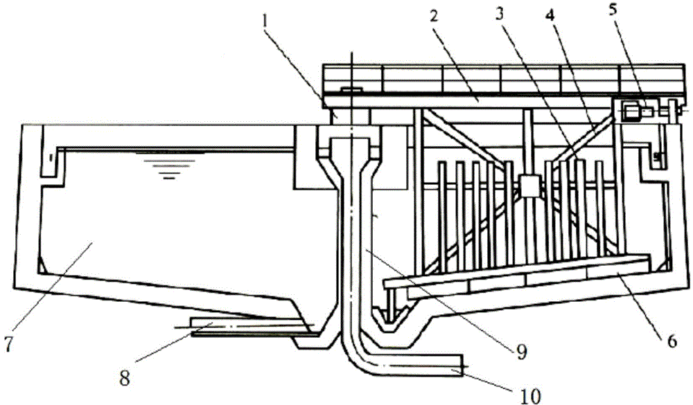
[0012] Such as figure 1 The peripheral transmission concentrated mud scraper shown includes a pool body 7, a central rotating support 1, a main beam 2, a transmission device 5 and a scraper 6. The bottom of the pool body 7 is conical, and the pool body 7 The bottom of the body 7 is provided with a mud outlet pipe 8, the pool body 7 is a half-span structure, the center column 9 and the water inlet pipe 10 are arranged in the middle of the pool body 7, and the water inlet pipe 10 is parallel to the center column 9 Set, the upper end of the central column 9 is provided with a central rotating support 1, one end of the main beam 2 is connected to the central rotating support 1, and the other end is equipped with a transmission device 5, and the transmission device 5 is connected to the hinged scraper The arm 4 is connected, and the bottom of the hinged scraper arm 4 is connected to the scraper 6, and the vertical grid bar 3 is also arranged on the scraper 6. The scraper 6 has a s...


PUM


Abstract

The invention discloses a peripheral transmission concentration mud scraper which comprises a pond body, a center rotating support, a main beam, a transmission device and a scraper plate, wherein the pond body is of a half-straddle type structure, a center upright and a water inlet pipe are arranged in the middle of the pond body, the water inlet pipe and the center upright are arranged in parallel, the center rotating support is arranged at the upper end of the center upright, one end of the main bam is connected with the center rotating support, the transmission device is arranged at the other end of the main beam, the transmission device is connected with a hinged scraping arm, the bottom of the hinged scraping arm is connected with the scraping plate, and vertical gird bars are arranged on the scraping plate. The peripheral transmission concentration mud scraper is simple in structure; water enters from the center and is discharged from the periphery, and mud is discharged from the bottom of the center, the vertical grids mainly play roles in slow carding and coagulating, so that the sludge compactness is improved. By adopting the hinged scraping arm, the effect of overload protection is played, the operation cost is effectively lowered; a truss girder is light in mass and good in rigidity; the scraper plate is arranged spirally, so that the mud scraping effect is relatively good.

Description

technical field [0001] The invention relates to the field of sewage treatment, in particular to a peripheral drive thickening mud scraper. Background technique [0002] Peripheral drive thickening sludge scraper is suitable for radial flow primary or secondary sedimentation tanks in sewage treatment plants. Its main function is to scrape the sludge settled at the bottom of the tank to the central mud pit, and then discharge it through the sludge discharge pipe to facilitate the sludge backflow Or concentrated dehydration, the mud scraper set under the main beam is driven by the drive mechanism installed on the periphery, and rotates around the center support installed on the center support of the pool, and the sludge settled at the bottom of the pool is collected by the scraper to the center The mud pit is discharged out of the pool by the mud discharge pipe. In the prior art, the amount of concentrated sludge in the surrounding thickened mud scraper is relatively large, so ...

Claims


Application Information

Patent Timeline
Patent Type & Authority Applications(China)
IPC IPC(8): B01D21/18
Inventor 周建国夏利荣
Owner CHANGZHOU LIWEI KNIFE
Learn More