Microwave reaction device using coaxial leaky antenna and application of microwave reaction device using coaxial leaky antenna

A microwave reaction and crack antenna technology, applied in the microwave field, can solve problems such as instrument damage, probe breakdown, uneven microwave distribution, etc.

Inactive Publication Date: 2015-03-04
EAST CHINA UNIV OF SCI & TECH
View PDF9 Cites 13 Cited by
  • Summary
  • Abstract
  • Description
  • Claims
  • Application Information

AI Technical Summary

Problems solved by technology

However, the microwave energy mainly depends on the radiation from the tip of the probe, which can only increase the uniformity to a certain extent. If the scale of the material continues to increase, the problem of uneven distribution of microwaves will occur
At the same time, another important issue in using the probe to radiate microwaves is the energy conversion efficiency of the probe. With the increase of the microwave power, the energy conversion efficiency will usually be greatly reduced. If the probe is to obtain higher output power, then Requires more input power, resulting in large energy losses due to reduced conversion efficiency
Moreover, the probe mainly relies on the top radiation, and most of the microwave energy is concentrated there. As the power increases, the load on the probe gradually increases. If the power is too high, the probe may not be able to withstand it and will be broken down. causing damage to the instrument
[0006] It can be seen that there are still certain limitations and defects in the application of existing microwave heating devices, and it is difficult to efficiently apply to various chemical reaction processes, especially industrial processes, while ensuring microwave uniformity.

Method used


Image

  • Microwave reaction device using coaxial leaky antenna and application of microwave reaction device using coaxial leaky antenna
  • Microwave reaction device using coaxial leaky antenna and application of microwave reaction device using coaxial leaky antenna
  • Microwave reaction device using coaxial leaky antenna and application of microwave reaction device using coaxial leaky antenna

Examples


Embodiment 1

[0101] Example 1: Detection of Microwave Distribution Uniformity

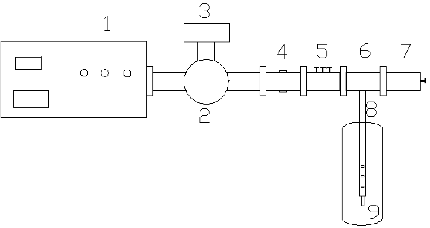
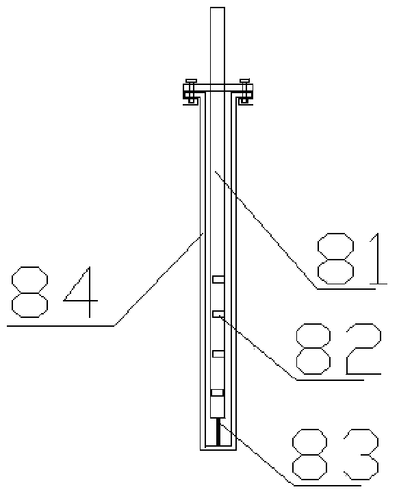
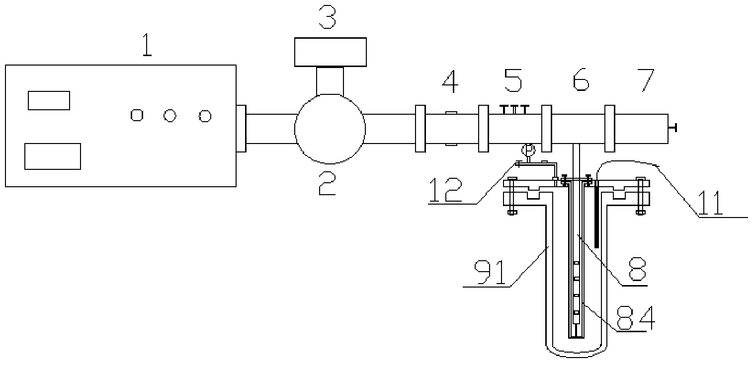
[0102] according to image 3 As shown, connect No. 2 microwave reaction device (wherein, the reactor part is composed of Figure 7 replace the structure shown), put the coaxial antenna into the intermittent stirred reactor of the No. 2 device with 3L deionized water, without stirring, turn on the microwave power supply under normal pressure, and set the power to 2×1.5 kW, adjust the three-screw adjuster and the terminal short-circuit adjuster to maximize the incident / reflected current ratio. During the radiation process, multiple optical fiber thermometers are used to detect the temperature at different positions at the same time. The maximum temperature difference in the circumferential direction of the antenna is 0.3°C. The maximum temperature difference in the vertical direction is 0.8°C, the maximum temperature difference in the radial direction of the antenna is 2.7°C, and the maximum temperature differen...

Embodiment 2

[0107] Embodiment 2: the application of stirring type reactor

[0108] (1) Atmospheric pressure application and scale up

[0109] Put 0.5mol benzaldehyde, 0.5mol acetophenone, 0.25mol sodium hydroxide and 250mL deionized water into the intermittent stirring reactor of No. 1 microwave reaction device, according to image 3 Connect the microwave reaction device as shown and connect the condensing reflux system, set the stirring speed to 200rpm, turn on the microwave power source under normal pressure, set the power to 3kW, and measure the temperature with an optical fiber thermometer during the heating process. After the reaction solution boiled, the power was adjusted to reflux the reaction solution for 40 min. After the reaction, the microwave power source was turned off, and the reaction solution was processed to finally obtain chalcone with an isolated yield of 88%.

[0110] 5mol benzaldehyde, 5mol acetophenone, 2.5mol sodium hydroxide and 2.5L deionized water are dropped i...

Embodiment 3

[0118] Embodiment 3: the application of internal circulation reactor

[0119] Put 0.4mol of malononitrile, 0.2mol of acetophenone and 300mL of deionized water into the batch-type internal circulation reactor of No. 1 microwave reaction device, according to image 3 The microwave reaction device connected as shown (wherein, the reactor part is composed of Figure 5 The structure shown is replaced) and connected to the condensing reflux system. Under normal pressure, turn on the microwave power source, set the power to 3kW, and measure the temperature with an optical fiber thermometer during the heating process. After the reaction solution boils, adjust the power to make the reaction solution boil and circulate for 40 minutes. After the reaction was completed, the microwave power source was turned off, and the reaction solution was processed to finally obtain 2-(1-phenylethylidene)malononitrile with an isolated yield of 85%.

[0120] 4mol of malononitrile, 2mol of acetophenone...


PUM

PropertyMeasurementUnit
lengthaaaaaaaaaa
lengthaaaaaaaaaa
lengthaaaaaaaaaa

Abstract

The invention provides a microwave reaction device using a coaxial leaky antenna and application of the microwave reaction device using the coaxial leaky antenna. The device comprises a microwave heating device and a reactor, wherein the microwave heating device comprises a microwave generation and transmission device and the coaxial leaky antenna; the microwave generation and transmission device comprises a microwave power source, an annular device, a false load, a microwave power detection device, a coaxial converter and a microwave tuning device; the coaxial leaky antenna is connected to the coaxial converter, and extends into from any end of the reactor, so that microwaves are fed back into the reactor. The device provided by the invention is high in microwave energy coaxial conversion efficiency, is uniform in microwave distribution in the reactor, can be applied to any reaction for heating by utilizing the microwaves, and is especially suitable for large-scale microwave reaction.

Description

technical field [0001] The invention belongs to the microwave field. Specifically, the present invention relates to a microwave reaction device using a coaxial slot antenna and its application, in particular to a microwave-heated reactor and its application in amplification and industrialization. Background technique [0002] Microwave refers to electromagnetic waves with a frequency of 300MHz to 300GHz. Compared with traditional heating methods, microwave has the characteristics of fast heating speed, high thermal efficiency, and uniform heating. Microwave heating does not need to directly contact the material. The high-frequency reciprocating motion of the dipole molecules inside the material generates similar "internal friction heat" to increase the temperature of the material. It does not require any heat conduction process to simultaneously heat up the inside and outside of the material. [0003] At present, there are many kinds of microwave chemical reaction devices a...

Claims


Application Information

Patent Timeline
Patent Type & Authority Applications(China)
IPC IPC(8): B01J19/12H05B6/72
CPCB01J19/12H05B6/72B01J19/126B01J2219/00141B01J2219/1206C07C45/74C07C241/04C07C253/30C07D311/16C07C49/796C07C255/34C07C243/38
Inventor 宋恭华林盛杰彭延庆李钰王圣伟
Owner EAST CHINA UNIV OF SCI & TECH
Why Eureka
Try Eureka