
Blanking mold of motor stator punching sheet with sheet buckling groove

A technology for motor stator and blanking die, which is applied in forming tools, manufacturing tools, metal processing equipment, etc., can solve the problems of inability to meet the quality requirements of high-end customers, misalignment of punching and lamination grooves, and inaccurate groove positions. To achieve the effect of easy promotion and use, reducing investment and improving production efficiency

Inactive Publication Date: 2015-03-04
JIANGSU TONGDA POWER TECH
View PDF9 Cites 2 Cited by
  • Summary
  • Abstract
  • Description
  • Claims
  • Application Information

AI Technical Summary

Problems solved by technology

[0002] With the development of science and technology, mold manufacturing is changing from the past labor-intensive and mainly relying on the manual skills of workers and the era of mechanical processing using traditional mechanical equipment to the current technology-intensive and more dependent on automation equipment, requiring high-precision The molds are matched. The traditional motor stator blanks first, and then installs the buckle groove mold on a 10-ton high-speed single-slot punching machine to punch the stator buckle groove. Generally, two people are required to operate at the same time, which is labor-intensive and difficult to produce. The efficiency is low, the repeated positioning of the punching sheet leads to inaccurate punching groove position, the groove shape misalignment of the punching sheet stack and the uneven groove shape of the buckle sheet, which cannot meet the quality requirements of high-end customers

Method used


Image

  • Blanking mold of motor stator punching sheet with sheet buckling groove

Examples


Embodiment Construction

[0019] The present invention is described in further detail now in conjunction with accompanying drawing. These drawings are all simplified schematic diagrams, which only illustrate the basic structure of the present invention in a schematic manner, so they only show the configurations related to the present invention.

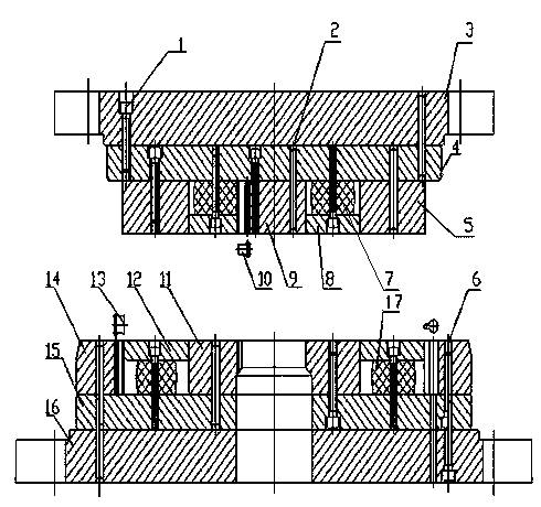
[0020] Such as figure 1 As shown, a blanking die for motor stator punching with buckle slots includes an upper die part and a lower die part, and the upper die part includes an upper bottom plate 3, an upper backing plate 4 and an upper concave-convex die 5. The upper concave-convex mold 5 is fixed under the upper backing plate 4, and the upper backing plate 4 is fixed under the upper bottom plate 3, and the lower mold part includes the lower bottom plate 16, the lower backing plate 15 and the lower concave-convex mold 11. The lower concave and convex mold 11 is fixed on the lower backing plate 15, and the lower backing plate 15 is fixed on the lower bottom p...


PUM


Abstract

The invention discloses a blanking mold of motor stator punching sheet with a sheet buckling groove. The blanking mold comprises an upper concave-convex mold and a lower concave-convex mold, wherein the middle of the upper concave-convex mold is provided with a rotor shaft hole male mold, a rotor key groove mold is arranged along the circumferential direction of the rotor shaft hole male mold, an upper concave ring is arranged around the outer side of the rotor shaft hole male mold, an upper elastic pad block is arranged in the upper concave ring, the lower side of the upper elastic pad block is connected with an upper discharging plate, the middle of the lower concave-convex mold is provided with a shaft hole in a position corresponding to the rotor shaft hole male mold, a stator excircle male mold is arranged at the excircle part of the lower concave-convex mold, a stator sheet buckling groove male mold is arranged along the inner diameter part of the stator excircle male mold, a lower concave ring is arranged around the outer side of the shaft hole, a lower elastic pad block is arranged in the lower concave ring, a lower discharging plate is connected onto the lower elastic pad block, and a sign groove male mold is also arranged on the lower concave-convex mold. Compared with the prior art, the blanking mold has the beneficial effects that the stator blanking and the processing in the buckling sheet groove can be simultaneously completed on one mold, and the work efficiency is improved.

Description

technical field [0001] The invention belongs to the field of stamping and manufacturing of motor stator punching sheets, and relates to a blanking die for motor stator punching sheets with buckle sheet grooves. Background technique [0002] With the development of science and technology, mold manufacturing is changing from the past labor-intensive and mainly relying on the manual skills of workers and the era of mechanical processing using traditional mechanical equipment to the current technology-intensive and more dependent on automation equipment, requiring high-precision The molds are matched. The traditional motor stator blanks first, and then installs the buckle groove mold on a 10-ton high-speed single-slot punching machine to punch the stator buckle groove. Generally, two people are required to operate at the same time, which is labor-intensive and difficult to produce. The efficiency is low, the repeated positioning of the punching sheet leads to the inaccurate posi...

Claims


Application Information

Patent Timeline
IPC IPC(8): B21D37/10B21D28/14
CPCB21D28/14B21D45/08
Inventor 马艳萍叶华王晓峰王岳胡浩胡欣荣
Owner JIANGSU TONGDA POWER TECH
Learn More