
Rotary positioning drilling clamp

A drilling jig and indexing technology, which is applied in the field of mechanical processing jigs, can solve problems such as complicated marking work, imprecise production efficiency, and affecting production quality and efficiency, and achieve the effects of compact and reasonable design structure, convenient operation, and simple structure

Active Publication Date: 2015-03-04
浙江德弘机电科技股份有限公司
View PDF6 Cites 6 Cited by
  • Summary
  • Abstract
  • Description
  • Claims
  • Application Information

AI Technical Summary

Problems solved by technology

[0004] According to the traditional hole processing method, in general, the technological process is roughly divided into: platform alignment, scribing, sample punching, clamping and drilling. This processing method is not refined and the production efficiency is low. Scribing work must be done before drilling. Because there are central holes in the center of disc sleeve parts, the scribing work is quite complicated. If the number of parts to be processed is not large and parts need to be replaced, frequent scribing and fixture replacement Seriously affect the production quality and efficiency
[0005] Therefore, the existing technology can no longer meet the needs of the existing production technology, and there is an urgent need for a clamp that can adapt to the drilling of disc sleeve parts, specifically a kind of indexable positioning drilling clamp.

Method used


Image

  • Rotary positioning drilling clamp
  • Rotary positioning drilling clamp
  • Rotary positioning drilling clamp

Examples


Embodiment Construction

[0024] In order to make the technical means, creative features, goals and effects achieved by the present invention easy to understand, the present invention will be further elaborated below.

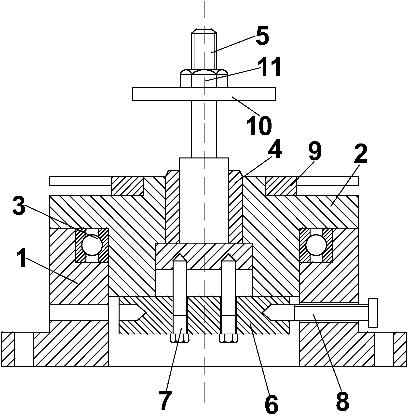
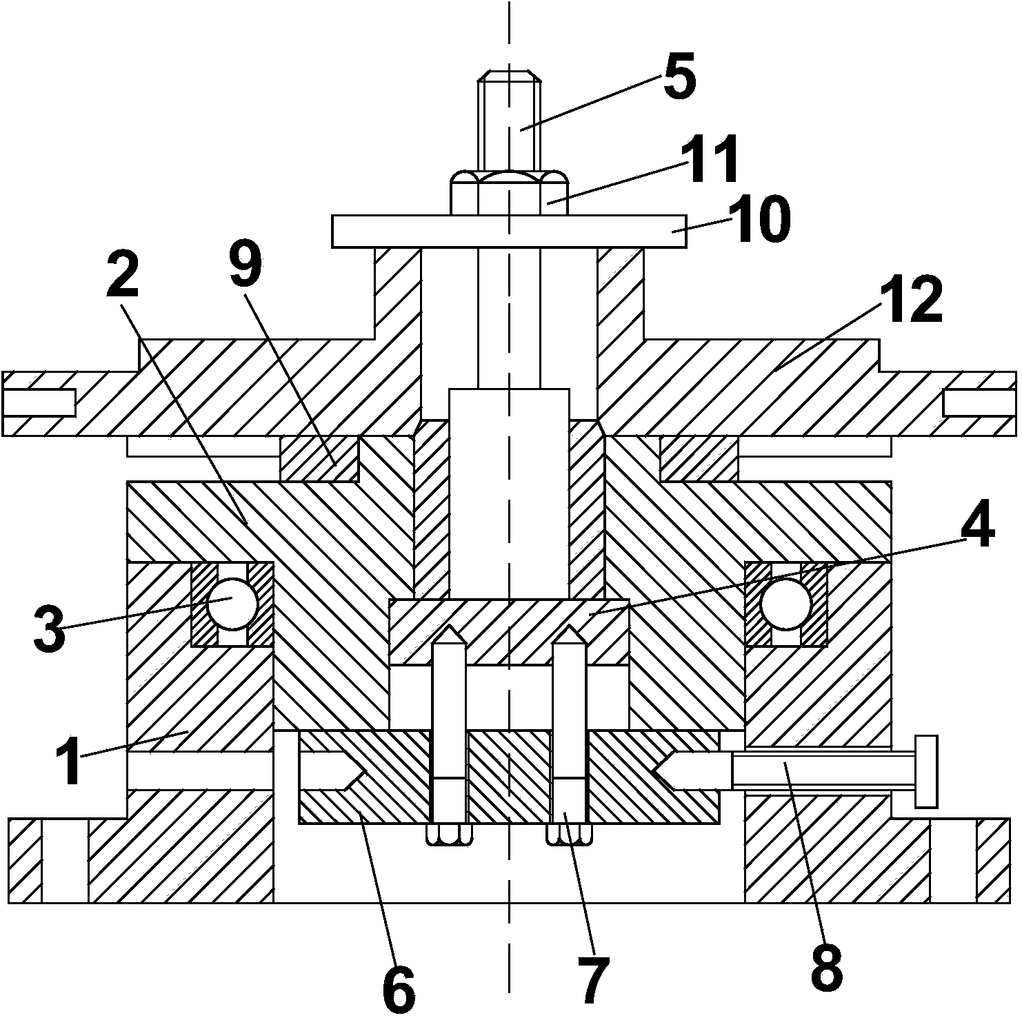
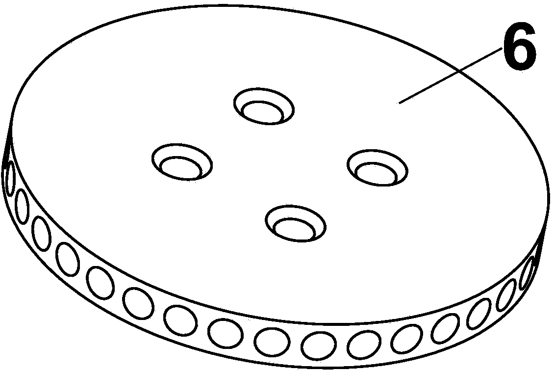
[0025] Such as figure 1 with figure 2 As shown, the above-mentioned indexable positioning drilling jig includes a base 1, a base 2, a rolling bearing 3, a sleeve 4, a movable mandrel 5, an indexing plate 6, an axial locking screw 7, a radial The locking pin 8, the chip removal disc 9, the pressure plate 10 and the locking bolt 11, a mounting plate is arranged under the base 1, and a mounting through hole is evenly opened in the radial direction of the mounting plate, and the mounting through hole is used in the present invention For grounding installation or fixed installation when used in conjunction with other parts, a fixing seat is provided above the base 1, and through holes are symmetrically opened at the lower end of the fixing seat, and the fixing seat is a hollow cylinder str...


PUM


Abstract

The invention relates to a rotary positioning drilling clamp, which comprises a bottom seat, a base, rolling bearings, a sleeve cylinder, a movable core shaft, an indexing disc, axial locking nuts, radial locking pins, a chip removal disc, a press plate and a locking bolt, wherein the base is arranged in a fixing seat on the bottom seat through the rolling bearings, a boss is arranged at the upper end of the base, the sleeve cylinder is fixedly arranged in the base, the movable core shaft is arranged in an opening at the upper end of the sleeve cylinder, the indexing disc is fixedly arranged at the sealing part of the lower end of the sleeve cylinder by the axial locking screws, the radial locking pins penetrate through the through hole in the fixing seat and are arranged on the indexing disc, the chip removal disc sleeves the boss on the base, the press plate is arranged on the movable core shaft, and the locking bolt is positioned at the upper end of the movable core shaft. The rotary positioning drilling clamp has the advantages that when a belt disc is drilled, the axial and radial locking functions of the belt disc are realized, and the circumferential equal dividing and drilling position determining effects of the belt disc are realized.

Description

technical field [0001] The invention relates to the field of machining fixtures, in particular to an indexable positioning drilling fixture. Background technique [0002] A fixture is a device used to fix the processing object in the process of mechanical manufacturing so that it occupies the correct position to accept construction or testing. In a broad sense, it is used to install the workpiece quickly, conveniently and safely in any process in the process. All devices can be called fixtures; such as welding fixtures, inspection fixtures, assembly fixtures, machine tool fixtures, etc. The types of fixtures can be divided into universal fixtures, special fixtures, adjustable fixtures and combination fixtures according to their characteristics. [0003] In the current mechanical processing field, the parts processed can be mainly divided into disc sleeves and round shafts. For the drilling of parts, it is necessary to use ordinary vertical radial drilling machines to process...

Claims


Application Information

Patent Timeline
Patent Type & Authority Applications(China)
IPC IPC(8): B23B47/00B23Q1/25B23Q16/02
CPCB23B47/00B23Q1/25B23Q16/02
Inventor 付建邹洪
Owner 浙江德弘机电科技股份有限公司
Learn More