Impeller blade and impeller upper plate laser welding method and clamping method and jig

An impeller blade and laser welding technology, which is applied in the field of laser welding and impeller laser welding, can solve problems such as low clamping efficiency, low degree of automation, and difficult clamping, so as to ensure quality, reduce clamping difficulty, and ensure positioning reliability and the effect of precision

Active Publication Date: 2015-03-04
HANS LASER TECH IND GRP CO LTD
View PDF7 Cites 21 Cited by
  • Summary
  • Abstract
  • Description
  • Claims
  • Application Information

AI Technical Summary

Problems solved by technology

[0007] The object of the present invention is to provide a fixture for laser welding of the impeller blade and the impeller upper plate, a clamping method for clamping the impeller blade and the impeller upper plate by using the clamp, and laser welding for clamping the impeller blade and the impeller upper plate by using the clamping method The method aims to solve the technical problems of poor versatility, difficult clamping, low clamping efficiency, low clamping positioning reliability, and low degree of automation of existing impeller laser welding fixtures

Method used


Image

  • Impeller blade and impeller upper plate laser welding method and clamping method and jig
  • Impeller blade and impeller upper plate laser welding method and clamping method and jig
  • Impeller blade and impeller upper plate laser welding method and clamping method and jig

Examples


Embodiment Construction

[0029] In order to make the object, technical solution and advantages of the present invention more clear, the present invention will be further described in detail below in conjunction with the accompanying drawings and embodiments. It should be understood that the specific embodiments described here are only used to explain the present invention, not to limit the present invention.

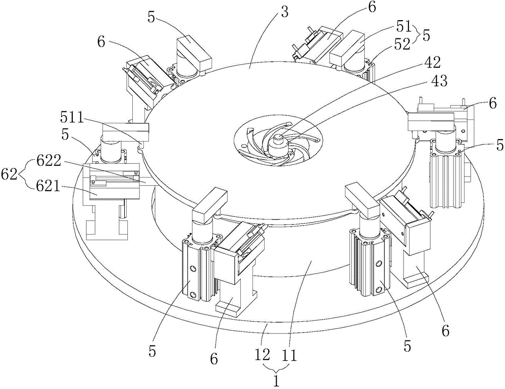
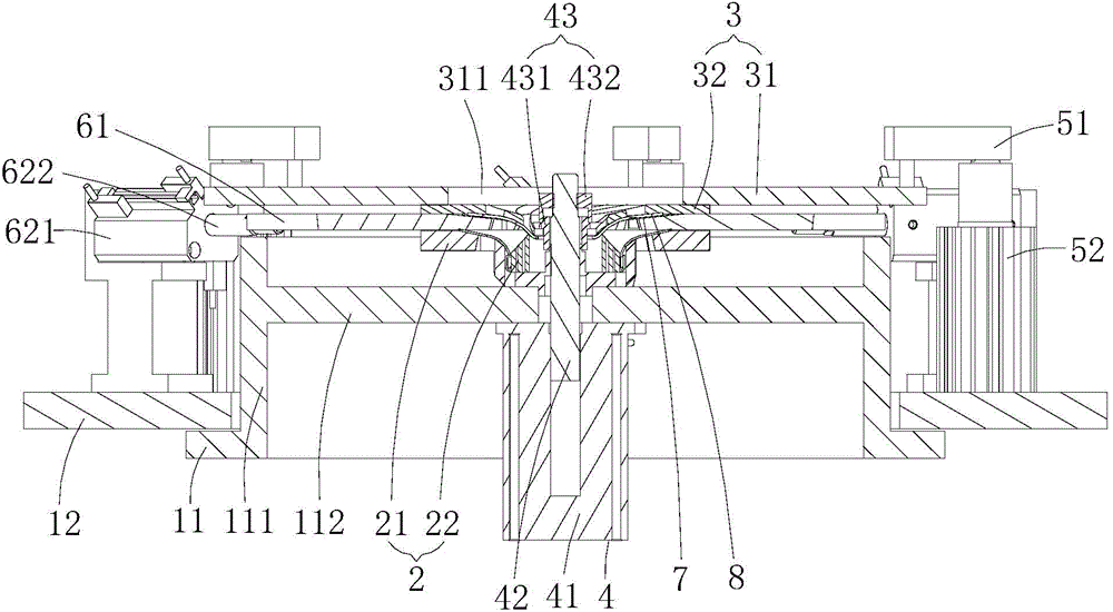
[0030] Such as figure 1 and figure 2 As shown, the fixture for laser welding the impeller blade and the impeller upper plate provided by the embodiment of the present invention includes a base assembly 1, a support assembly 2 installed on the base assembly 1 for placing and positioning the impeller blade 7 and the impeller upper plate 8, and the Above the support assembly 2, the impeller blade 7 and the impeller upper plate 8 are pressed against the pressure plate assembly 3 on the support assembly 2 in the axial direction of the base assembly 1. Compress the first telescopic assembly 4 of the ...


PUM


Abstract

The invention is applicable to the field of impeller laser welding and discloses an impeller blade and impeller upper plate laser welding jig, an impeller blade and impeller upper plate clamping method with the jig and an impeller blade and impeller upper plate laser welding method through the clamping method. The impeller blade and impeller upper plate laser welding jig comprises a base assembly, a support assembly mounted on the base assembly for placing and positioning an impeller blade and an impeller upper plate, a pressing plate assembly arranged above the support assembly for pressing the impeller blade and the impeller upper plate to the support assembly, a first telescoping assembly mounted on the base assembly for pressing the pressing plate assembly in the axial direction of the base assembly, a plurality of peripheral pressing structures mounted on the base assembly, and a plurality of lateral positioning structures mounted on the base assembly. The impeller blade and impeller upper plate laser welding jig, the impeller blade and impeller upper plate clamping method with the jig and the impeller blade and impeller upper plate laser welding method through the clamping method solve the technical problems of poor versatility, clamping difficulty and low clamping efficiency, clamping positioning reliability and automation degree of existing impeller laser welding jigs.

Description

technical field [0001] The invention belongs to the technical field of impeller laser welding, and in particular relates to a fixture for laser welding of an impeller blade and an impeller upper plate, a clamping method for clamping an impeller blade and an impeller upper plate by using the clamp, and a clamping method for clamping an impeller blade and an impeller upper plate. Plate laser welding method. Background technique [0002] The impeller is an important part of the pump, and its size and precision directly affect the mechanical properties, working efficiency and service life of the pump. There are two main structural forms of impellers: open impeller and closed impeller. Due to its high efficiency, the closed impeller is widely used in centrifugal pumps with high lift and high efficiency. There are two kinds of blades of centrifugal pump impellers: cylindrical and space twisted. The use of space twisted blades for centrifugal pump impellers can not only reduce th...

Claims


Application Information

Patent Timeline
Patent Type & Authority Applications(China)
IPC IPC(8): B23K37/04B23K26/21
CPCB23K26/24B23K37/0435B23K2101/001
Inventor 杨小玲任巨海唐景龙陈根余陈燚高云峰
Owner HANS LASER TECH IND GRP CO LTD
Why Eureka
Try Eureka