Inner cooling damping heat-shrinkable tool bar device

A technology of tool holder and heat shrinking, which is applied in positioning devices, milling cutters, clamping, etc., can solve the problems that do not involve heat shrinking tool holders and tool cooling, unbalance and vibration, etc., and achieve simple and reliable structure , good rigidity and good interchangeability

Inactive Publication Date: 2015-03-04
XIANGTAN UNIV
View PDF9 Cites 8 Cited by
  • Summary
  • Abstract
  • Description
  • Claims
  • Application Information

AI Technical Summary

Problems solved by technology

The heat-shrinkable handle can eliminate the imbalance caused by installation, but it does not solve technical problems such as imbalance and vibration caused by external forces in high-speed machining, nor does it involve solving technical problems such as heat-shrinkable handle and tool cooling

Method used


Image

  • Inner cooling damping heat-shrinkable tool bar device
  • Inner cooling damping heat-shrinkable tool bar device
  • Inner cooling damping heat-shrinkable tool bar device

Examples


Embodiment 1

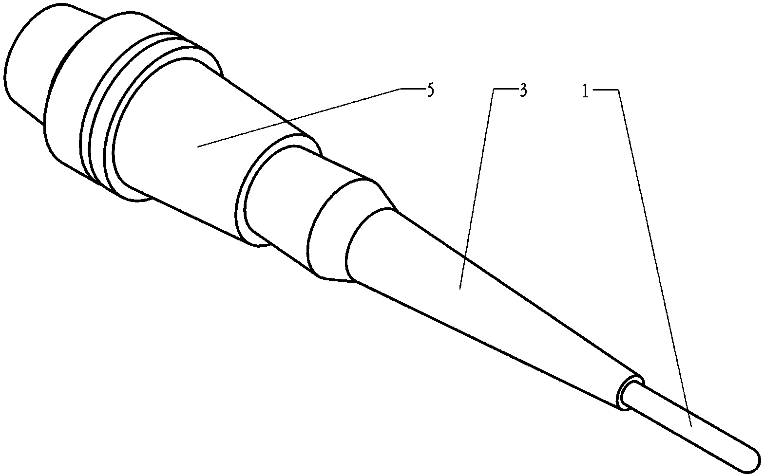
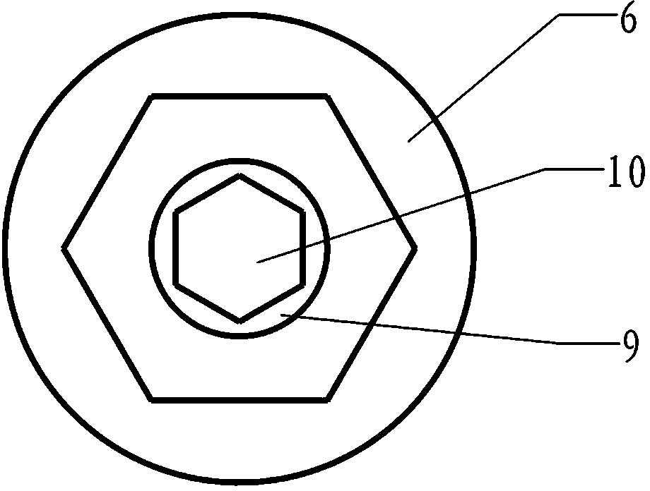
[0022] Example 1, such as figure 1 As shown, it includes a handle 5, a heat-shrinkable tool holder 3 and a tool 1; the inner end of the handle 5 is a shape structure matched with the spindle of the machining center, the handle 5 is designed as a hollow structure, and the handle 5 is a hollow cavity The waist is a screw through-hole structure with an inner diameter smaller than the inner diameter of both ends that matches the outer diameter of the connecting screw 6, and the outer end of the knife handle 5 is a tapered cavity structure that expands outward; The taper cavity at the outer end of the tool handle 5 is a tapered structure, and the inner end is provided with a screw hole; the inner end of the heat-shrinkable tool holder 3 is set in the outer end taper cavity of the tool handle 5, and the connecting screw rod 6 is used The inner end of the tool handle 5 is inserted through the through hole of the screw rod and connected with the screw hole provided at the inner end of...

Embodiment 2

[0023] Embodiment 2, in order to solve the technical problems encountered in lengthening the heat-shrinkable blade, the heat-shrinkable blade 3 of the present invention can adopt a double-cone structure with gradually smaller ends and a thicker waist. Compared with the traditional handle-knife mechanism, the length and size of the heat-shrinkable tool holder in the present invention are designed in series, and the rigidity is better, which makes the present invention can select suitable sizes according to different processing environments. Heat Shrink Arbor. refer to Figure 1 to Figure 6 , all the other are with embodiment 1.

Embodiment 3

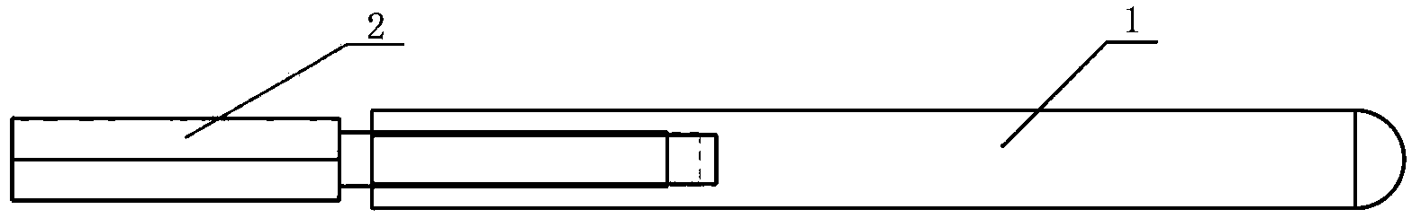
[0024] Embodiment 3, in order to improve the heat dissipation effect, the present invention may also be connected with a heat dissipation core 2 at the inner end of the cutting tool 1, and the heat dissipation core 2 may be a copper heat dissipation core with good thermal conductivity. The tail of the heat dissipation core 2 can also be designed as a wing structure to increase the heat dissipation area. refer to Figure 1 to Figure 6 , all the other are with above-mentioned embodiment 1 or 2.


PUM


Abstract

The invention discloses an inner cooling damping heat-shrinkable tool bar device, relates to the field of cutting machining, and mainly aims to solve the technical problems of high cost, easiness in causing pollution, easiness in generating vibration of a tool and the like caused by jetting of cooling liquid into an interference fit area in the conventional heat-shrinkable tool bar. According to the technical scheme, the inner cooling damping heat-shrinkable tool bar device comprises a tool shank (5), a heat-shrinkable tool bar (3) and a tool (1), wherein a conical cavity structure which stretches outwards is arranged at the outer end of the tool shank (5); the heat-shrinkable tool bar (3) is connected with a screw hole formed in the inner end of the heat-shrinkable tool bar (3) by inserting a connecting screw rod (6) into a screw rod through hole from the inner end of the tool shank (5); the inner end of the tool (1) is arranged at the outer end of the heat-shrinkable tool bar (3) in a sleeving way through interference hermetical fit; a cooling liquid cavity (4) is formed by the hollow inner cavity of the heat-shrinkable tool bar (3) between the connecting screw rod (6) and the tool (1); cooling liquid is packaged in the cooling liquid cavity (4). The inner cooling damping heat-shrinkable tool bar device is easy to install, detach and extend, and has high interchangeability; the adaptability of the inner cooling damping heat-shrinkable tool bar device as a machining device is well enhanced. The inner cooling damping heat-shrinkable tool bar is mainly applied to the field of deep cavity machining in a cutting machining process.

Description

technical field [0001] The patent of the present invention relates to the research field of cutting processing, in particular to an internal cooling shock absorbing heat shrinkable tool holder device for cutting processing equipment. Background technique [0002] At present, in the high-speed machining industry, although the usual tool holder-collet collet-tool system structure can meet the requirements of high-speed milling of general parts, it is restricted by the rigidity of the tool system, so that the tool can approach the workpiece during processing. The depth is greatly limited; heat-shrinkable tool holders are widely used, and the application of heat-shrinkable tool holders is also becoming mature. During high-speed cutting, cutting heat is transferred upward along the tool, and the temperature of the contact part of the heat-shrinkable holder (tool holder) rises. Since the heat-shrinkable tool holder (knife holder) and the tool are matched by heat-shrinkable interf...

Claims


Application Information

Patent Timeline
Patent Type & Authority Applications(China)
IPC IPC(8): B23Q3/12B23C5/26B23C5/28B23Q11/10
CPCB23C5/26B23C5/28B23Q3/12B23Q11/10
Inventor 周后明刘博秦衡峰张高峰周友行
Owner XIANGTAN UNIV
Why Eureka
Try Eureka