

Seven-degree-of-freedom external skeleton type teleoperation main hand
An exoskeleton and degree of freedom technology, which is applied in the direction of manipulators, program-controlled manipulators, joints, etc., can solve the problems of complex robot motion mapping, heavy human burden, and large inertia, and achieve the effect of compact structure, less fatigue, and adjustable size
- Summary
- Abstract
- Description
- Claims
- Application Information
AI Technical Summary
Problems solved by technology
Method used
Image

Examples
Embodiment Construction
[0024] Below in conjunction with accompanying drawing, the present invention is further described in detail:
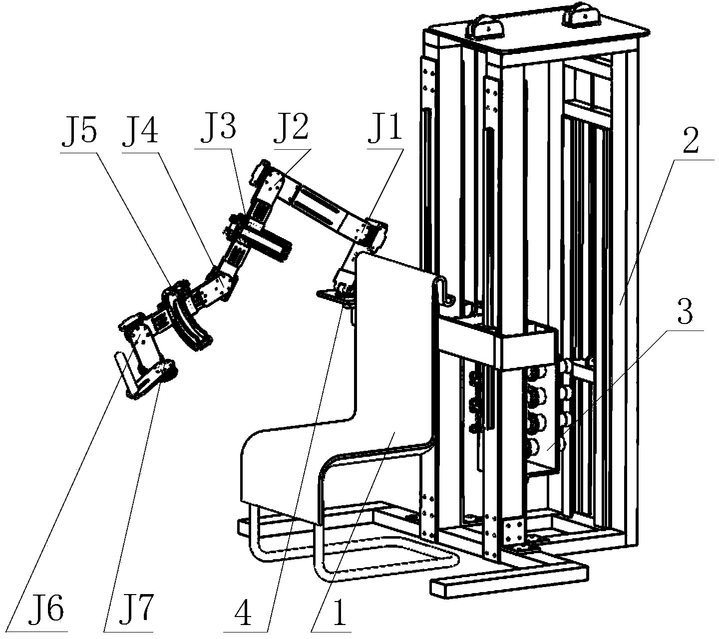
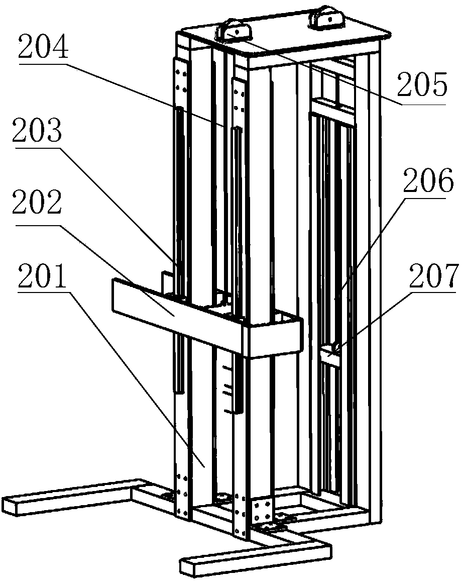
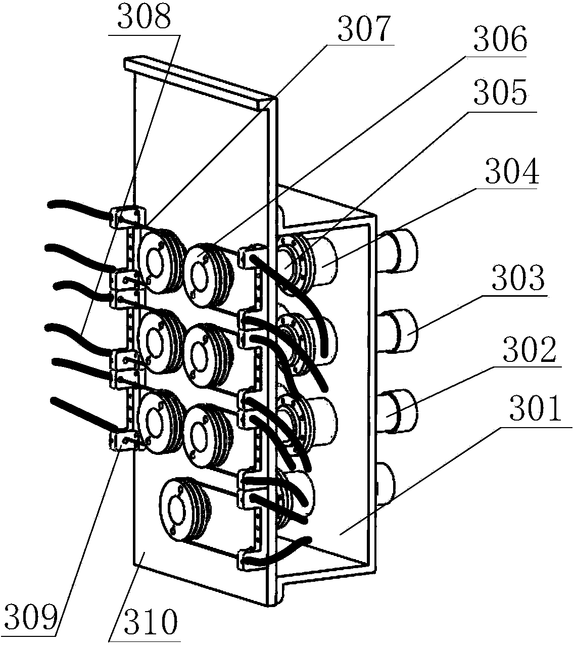
[0025] The present invention is an exoskeleton type teleoperation main hand device, and the arm wearing part has seven degrees of freedom. figure 1 Shown is the overall structure of the device. The exoskeleton type remote operation main hand device of the present invention is composed of support (2), drive unit (3), exoskeleton main hand ( Figure 4) consists of three parts. Wherein, the main hand part of the exoskeleton is divided into a singular configuration adjustment unit (4) and an arm wearing part. According to the principle of anthropomorphic design, the arm wearing part adopts a series structure and is worn on the upper arm of the operator, including the shoulder, elbow, and wrist. There are seven rotational degrees of freedom in total, and each rotational degree of freedom is distributed sequentially. Among them, the shoulder has three rotational degrees ...
PUM
 Abstract
Description
Claims
Application Information