Three-dimensional engraving machine

A three-dimensional engraving machine and frame technology, applied in decorative arts, processing models, etc., can solve the problems of unsmooth sliding of the engraving machine, low transmission precision, and difficult realization of the engraving machine, and achieve stable tool holder, strong applicability, Easy-to-control effects

Active Publication Date: 2015-03-04
吴善旺
View PDF7 Cites 9 Cited by
  • Summary
  • Abstract
  • Description
  • Claims
  • Application Information

AI Technical Summary

Problems solved by technology

[0003] For example, the Chinese invention patent application (application number: 200810060107.X) discloses a three-dimensional engraving machine, which belongs to the field of mechanical technology. The three-dimensional engraving machine includes a frame and a crossbeam fixed on the top of the A tool rack for installing several knives is arranged on the top, a horizontal carriage connected by a horizontal guide rail is arranged between the tool rack and the beam, and a vertical carriage arranged vertically is arranged between the horizontal carriage and the tool rack. The vertical drag block connected with the guide rail, the tool holder is fixed on the vertical drag block, and the working platform is set under the beam, and the workpiece clamping mechanism with the same number as the number of tools is set on the working table. The longitudinal guide rails placed horizontally and vertically are connected, and the drive mechanism 3 for driving the workbench to move along the longitudinal guide rails is installed on the frame. However, in the actual engraving process, the head of the above-mentioned engraving machine is always vertically downward, and it can only realize the adjustment and movement in the front, rear, left, right, and up and down directions.

Method used


Image

  • Three-dimensional engraving machine
  • Three-dimensional engraving machine
  • Three-dimensional engraving machine

Examples


Embodiment 1

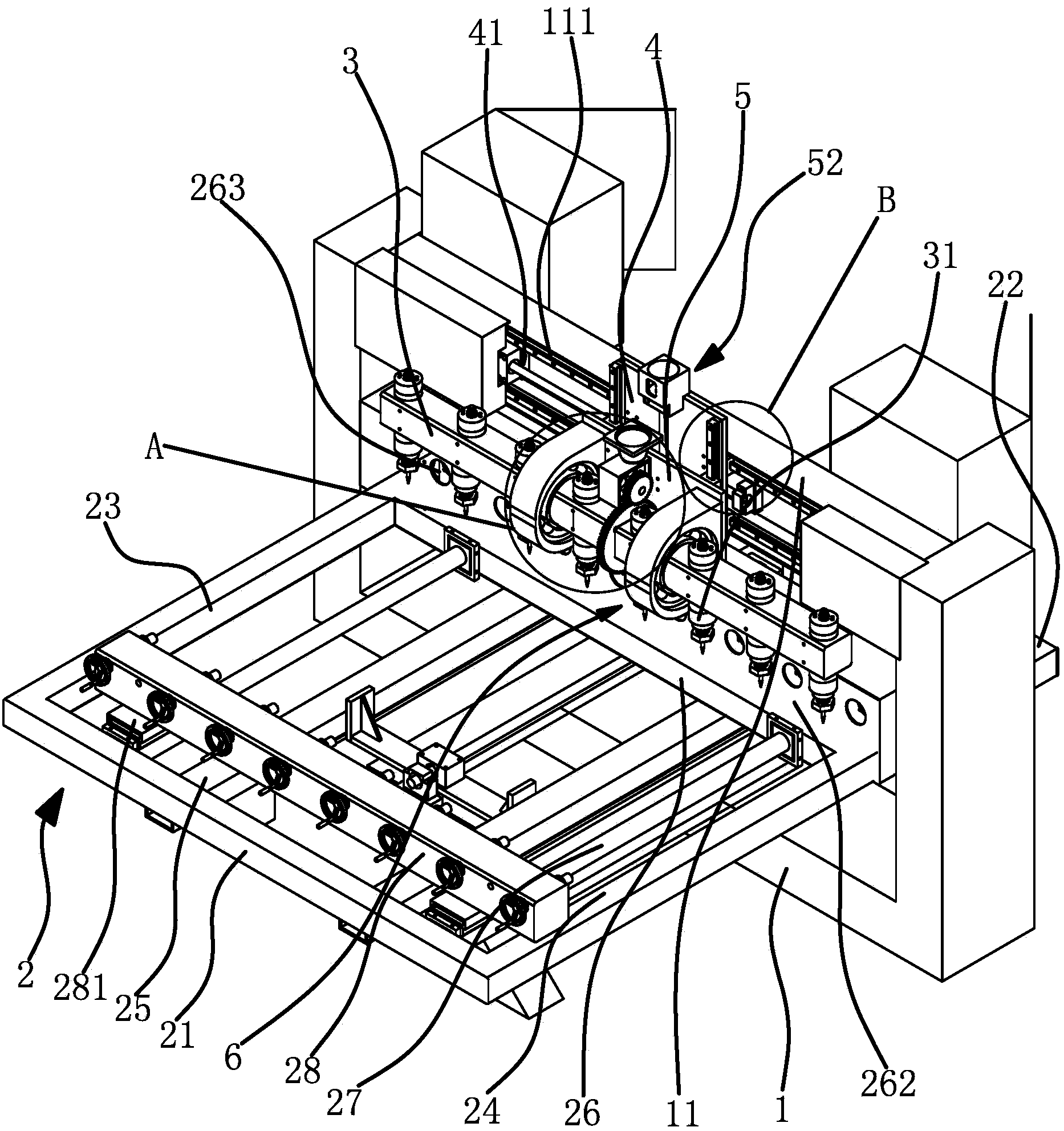
[0031] Such as figure 1 As shown, a three-dimensional engraving machine is used for engraving cylindrical workpieces, including a frame 1 and a workbench 2. The workbench 2 is arranged on the frame 1 and can move back and forth along the horizontal and vertical directions. The longitudinal direction of the platform 2 is fixed on the workbench 2, and a plurality of workpieces are arranged along the transverse direction of the workbench 2. There is a crossbeam 11 arranged horizontally along the top of the workbench 2, and the side of the crossbeam 11 is provided with a tool holder 3, and the tool holder 3 is elongated, and is used to install some cutters 31, that is, the machine head. One workpiece is opposite, that is, one cutter 31 is responsible for the engraving of one workpiece. On the side of the beam 11, there is a horizontal carriage 4 that can reciprocate horizontally and horizontally. On the horizontal carriage 4, there is a vertical carriage 5 that can reciprocate al...

Embodiment 2

[0037] The structure of the three-dimensional engraving machine is basically the same as that of Embodiment 1, the difference is that Figure 5 As shown, the driving mechanism 6 includes a motor 61, a worm screw 65 fixed on the rotating shaft of the motor 61 and coaxial with the rotating shaft of the motor 61, and a worm wheel 64 fixed on the tool rest 3, the worm wheel 65 is engaged with the worm wheel 64, and the worm wheel 65 The length direction of the worm gear is vertically downward and meshed with the worm gear, and the worm gear is fixed on the tool holder 3 and coaxial with the tool holder 3, so the rotation of the worm screw 65 can be converted into the rotation of the worm gear, and the structure is stable.

Embodiment 3

[0039] The structure of the three-dimensional engraving machine is basically the same as that of Embodiment 1, the difference is that Figure 6 As shown, the driving mechanism 6 includes a motor 61, a driving pulley 66 fixed on the rotating shaft of the motor 61 and a driven pulley 67 fixed on the tool rest 3, and the driven gear 63 is a driven belt whose diameter is greater than that of the driving pulley 66 Wheel 67, driving pulley 66 and driven pulley 67 are connected by transmission belt 68, that is, tool holder 3 is connected and driven by transmission belt 68, which has good speed regulation ability, and simple and effective structure.


PUM


Abstract

The invention provides a three-dimensional engraving machine, and belongs to the technical field of mechanical equipment. The three-dimensional engraving machine solves the problem that the angle regulation of a machine head is difficult to realize in the moving engraving process of the existing three-dimensional engraving machine. The three-dimensional engraving machine comprises a machine frame and a work table, wherein a cross beam is arranged above the work table, a cutter frame is arranged at the side part of the cross beam, a transverse dragging plate is arranged on the side surface of the cross beam, a vertical dragging plate capable of doing reciprocating movement in the vertical direction is arranged on the transverse dragging plate, a bearing seat is fixedly arranged on the vertical dragging plate, the cutter frame is connected with the bearing seat through a bearing, and a driving mechanism capable of driving the cutter frame to do reciprocating swinging by using the axial line of the cutter frame in the long strip direction as the axis center is arranged on the vertical dragging plate. The three-dimensional engraving machine has the advantages that the angle regulation of the machine head can be realized in the moving engraving process, so that the machine head can be used for engraving a product in different angles.

Description

technical field [0001] The invention belongs to the technical field of mechanical equipment and relates to a three-dimensional engraving machine. Background technique [0002] From the processing principle, engraving is a combination of drilling and milling. It has a wide range of applications, including woodworking engraving machines, laser engraving machines, advertising engraving machines, jade engraving machines, stone engraving machines, cylindrical engraving machines, etc. Three-dimensional engraving machine is an industry classification of engraving machine. It is a new type of CNC equipment in recent years. Its working principle is very similar to that of CNC milling machine. The engraving effect, the three-dimensional engraving machine has a wide range of applications, and even replaces the manual engraving technology, laying the foundation for mass and rapid production of products. [0003] For example, the Chinese invention patent application (application number:...

Claims


Application Information

Patent Timeline
Patent Type & Authority Applications(China)
IPC IPC(8): B44B1/00B44B1/06
Inventor 吴善旺
Owner 吴善旺
Why Eureka
Try Eureka