Trace dual-tube needle valve

A double-tube needle and trace technology, which is applied to multi-port valves, valve devices, mixers, etc., can solve the problems of difficult to control the accuracy of polyurethane glue feeding, poor product performance and appearance quality, affecting the ratio and mixing effect, etc. The effect of ideal mixing effect, consistent appearance and good product performance

Active Publication Date: 2015-03-04
DALIAN HUAGONG INNOVATION TECH
View PDF5 Cites 13 Cited by
  • Summary
  • Abstract
  • Description
  • Claims
  • Application Information

AI Technical Summary

Problems solved by technology

[0002] At present, the needle valves used for two-component polyurethane gluing equipment at home and abroad use independent conveying channels to transport polyurethane A and polyurethane B separately, and stir them evenly in the mixing device. When the proportion of polyurethane of the two components differs greatly, It is not easy to control the precision of two-component polyurethane glue feeding, which affects the ratio and mixing effect. Especially for trace or foamed polyurethane, the high-precision glue supply pump is used to meter the glue, and the mixing effect is not ideal, which is easy to cause product performance and Poor appearance

Method used


Image

  • Trace dual-tube needle valve
  • Trace dual-tube needle valve

Examples


specific Embodiment approach 1

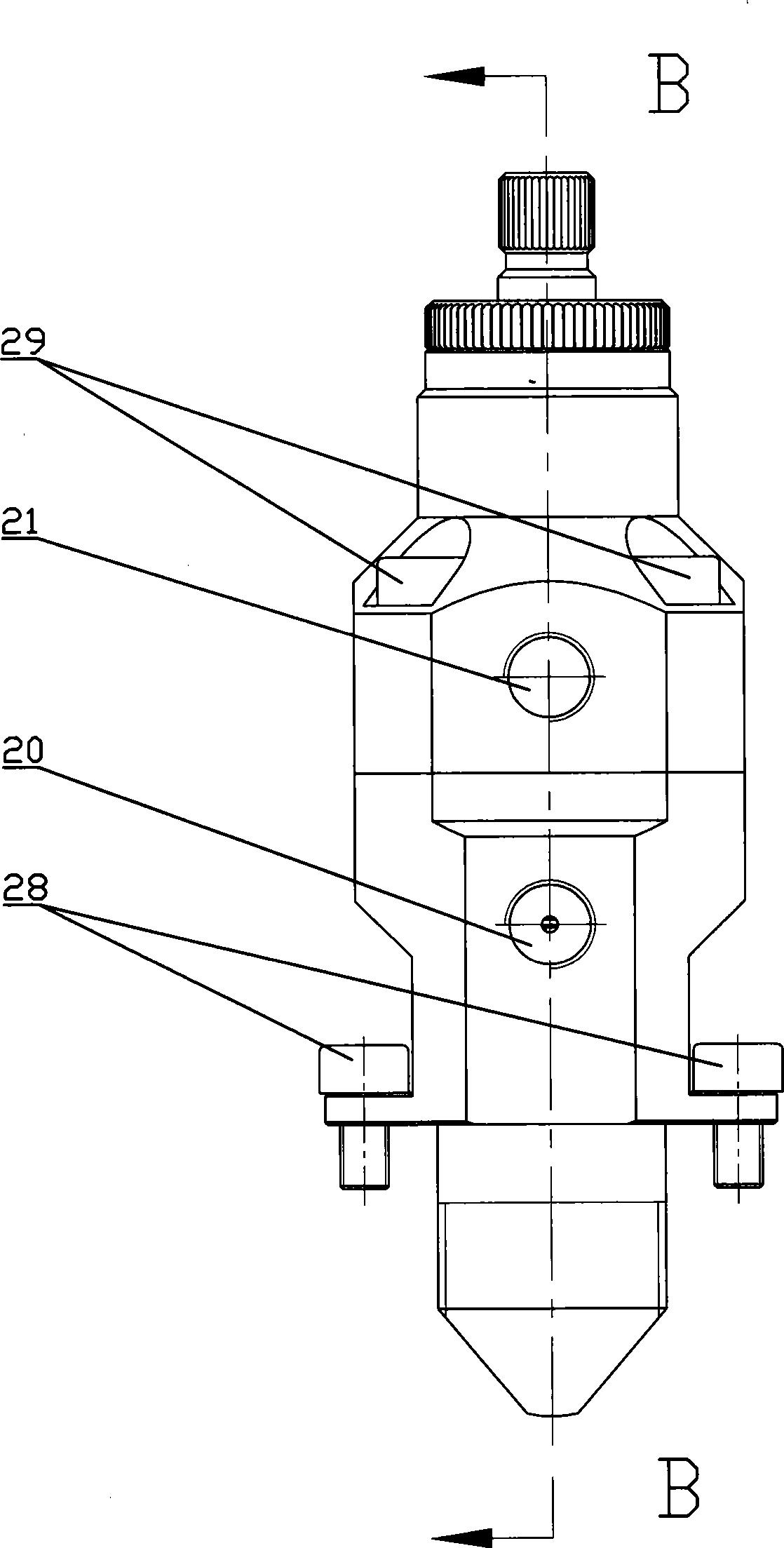
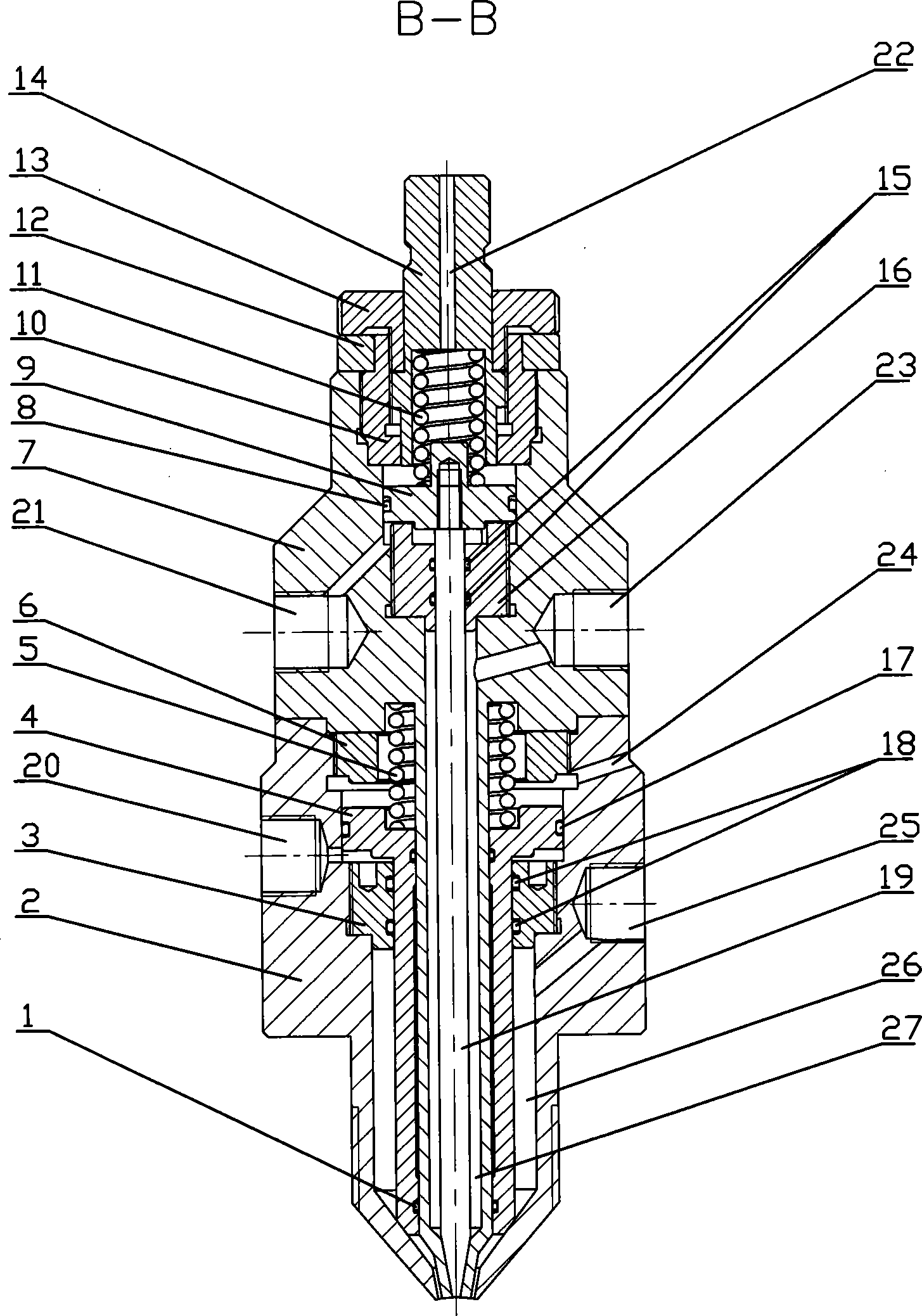
[0010] Specific implementation mode one: as figure 1 , 2 As shown, the micro double-tube needle valve includes a needle valve seat 2, a sealing plug 3, a piston A4, a spring A5, a retaining ring 6, a valve body 7, a piston B9, an inner sleeve 10, a spring B11, a gasket 12, an adjustment Nut 13, adjusting screw 14, seal head 16, valve needle 19, valve body 7 and needle valve seat 2 are fixedly connected by screw B29, retaining ring 6 and sealing plug 3 are fixed in needle valve seat 2 by threads respectively, piston A4 The piston part is installed between the retaining ring 6 and the sealing plug 3, the spring A5 is installed between the valve body 7 and the piston A4, the piston A4 can move up and down, the outer tapered surface of the lower end of the piston A4 and the lower end of the needle valve seat 2 The taper fits to seal and is used to close or open the A glue channel 26; the inner sleeve 10 and the head 16 are installed in the upper part of the valve body 7 with thre...

specific Embodiment approach 2

[0013] Specific implementation mode two: as figure 1 , 2 As shown, in the present embodiment, the micro double tube needle valve also includes II air inlet 20, I air inlet 21, through hole A22, glue inlet B23, through hole B24, glue inlet A25, A glue The channel 26 is located in the center of the B glue channel 27, the glue inlet B23 communicates with the B glue passage 27, the glue inlet A25 communicates with the A glue passage 26, the II air inlet 20, the I air inlet 21, the glue inlet A25 and The glue inlets B23 are respectively provided with connecting threads. When the polyurethane B enters the glue inlet B23, the compressed air enters the I air inlet 21, the piston B9 and the valve needle 19 move upward, and the taper surface at the lower end of the valve needle 19 and the valve body The lower cone surface of 7 is separated, polyurethane B flows out from the lower end of valve body 7, when the air inlet 21 of I is not ventilated, piston B9 is under the action of spring ...

specific Embodiment approach 3

[0014] Specific implementation mode three: as figure 2 As shown, in this embodiment, the micro-volume double-tube needle valve also includes a sealing ring B8 set on the piston B9, a sealing ring D17 set on the piston A4, a sealing ring A1 installed on the lower end of the piston A4, and a sealing ring installed on the piston A4. The sealing ring C15 on the sealing head 16 and the sealing ring E18 installed on the sealing plug 3 are made of solvent-resistant materials such as polyurethane or polytetrafluoroethylene or rubber.


PUM


Abstract

The invention provides a trace dual-tube needle valve and relates to a needle valve for gluing equipment, in particular to a trace dual-tube needle valve for dual-component polyurethane. The trace dual-tube needle valve comprises a needle valve base, a seal plug, a piston A, a spring A, a baffle ring, a valve body, a piston B, an inner sleeve and the like, wherein the valve body is fixedly connected with the needle valve base; the baffle ring and the seal plug are respectively and fixedly arranged in the needle valve base by virtue of threads; a piston part of the piston A is arranged between the baffle ring and the seal plug; the piston A is used for closing or opening a glue passage A; the inner sleeve and a seal head are respectively arranged at the upper part of the valve body by virtue of threads; a washer is arranged at the upper end of the inner sleeve; external threads of an adjusting nut and an adjusting screw are sequentially connected with internal threads of the inner sleeve; a valve needle is used for closing or opening a glue passage B. The trace dual-tube needle valve is relatively accurate in measuring accuracy, applicable to trace dual-component polyurethane gluing, especially applicable to trace foaming dual-component polyurethane gluing and also applicable to other trace dual-component adhesive gluing, and the measuring accuracy of the trace dual-component polyurethane inlet glue can be easily controlled.

Description

technical field [0001] The invention relates to a needle valve for gluing equipment, in particular to a micro-volume double-pipe needle valve for two-component polyurethane. Background technique [0002] At present, the needle valves used for two-component polyurethane gluing equipment at home and abroad use independent conveying channels to transport polyurethane A and polyurethane B separately, and stir them evenly in the mixing device. When the proportion of polyurethane of the two components differs greatly, It is not easy to control the precision of two-component polyurethane glue feeding, which affects the ratio and mixing effect. Especially for trace or foamed polyurethane, the high-precision glue supply pump is used to meter the glue, and the mixing effect is not ideal, which is easy to cause product performance and poor quality. Poor appearance quality. Contents of the invention [0003] In order to solve the above-mentioned problems, the present invention provid...

Claims


Application Information

Patent Timeline
Patent Type & Authority Applications(China)
IPC IPC(8): F16K11/20B01F7/00B01F15/04
CPCF16K11/20B01F27/00B01F35/80
Inventor 韩毅军时丕林刘桂红
Owner DALIAN HUAGONG INNOVATION TECH
Why Eureka
Try Eureka