Composite PE (Poly Ethylene) gas pipe

A gas pipe, gas technology, applied in the direction of pipes, pipe components, rigid pipes, etc., can solve the problems of low compressive strength, no installation, low safety performance, etc., to prevent aging and bending deformation, improve service life, pipe The effect of simple body structure

Inactive Publication Date: 2015-03-04
GUANGXI JINSHENG TECH DEV
View PDF7 Cites 5 Cited by
  • Summary
  • Abstract
  • Description
  • Claims
  • Application Information

AI Technical Summary

Problems solved by technology

However, due to the limitations of PE gas pipe materials and structures, PE gas pipes have some disadvantages: poor impact resistance, low compressive strength, easy to be affected by climate temperature, leakage cannot be found in time, difficult to detect leak points, and vulnerable to termites, etc. Insect-eaten, intolerant to sunlight, etc.
Although the invention is equipped with a metal mesh layer, an insect-proof layer and an alarm, which improves the pressure resistance of the pipe body, prevents pests from eating and improves safety precautions, but has the following deficiencies: First, the PE gas pipe is easily affected by the climate temperature and is not stable. It is resistant to sunlight, and the pipe is not equipped with protective layers such as heat insulation and heat preservation, so the pipe body is easily deformed and aged, which affects the service life; second, the pipe is only equipped with an alarm at the end, and it is convenient to detect related configurations when there is no leakage. It is not easy to check the leak point, and it is difficult to repair; in addition, the pipe is only equipped with a flame-retardant rubber inner layer, and there is no relevant sealing and anti-leakage measures, so the safety performance is not high

Method used


Image

  • Composite PE (Poly Ethylene) gas pipe
  • Composite PE (Poly Ethylene) gas pipe

Examples


Embodiment Construction

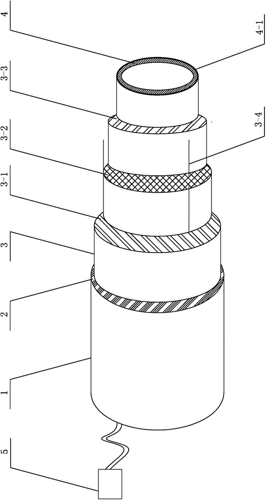
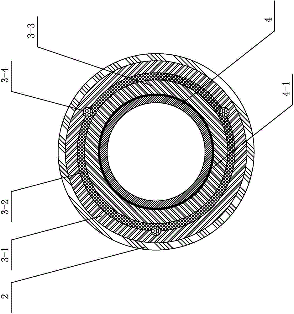
[0019] Such as figure 1 and figure 2 As shown, a specific embodiment of the present invention is proposed, a PE composite gas pipe, including a pipe body 1, and the pipe body 1 is an anti-corrosion layer 2, a base layer 3, and a rubber layer 4 for gas from the outside to the inside; The etching layer 2 is made of matrix resin and modified auxiliary materials.

[0020] Such as figure 1 As shown, the base layer 3 includes a PE outer layer 3-1, a metal mesh core layer 3-2, a PE inner layer 3-3, and a plurality of roots are arranged between the PE outer layer 3-1 and the metal mesh core layer 3-2. The metal wire 3-4 extending axially along the tube body 1 to both ends of the tube body 1, the metal wire 3-4 is evenly distributed on the outer peripheral surface of the metal mesh core layer 3-2, one end of the metal wire 3-4 is connected to the tube The detector alarm 5 at the end of the body 1 is connected; the preferred setting of the present embodiment is that the PE outer lay...


PUM


Abstract

The invention discloses a composite PE gas pipe. The composite PE gas pipe comprises a pipe body. The pipe body is composed of a corrosion resistant layer, a base layer and a gas rubber layer from outside to inside. The corrosion resistant layer is made of matrix resin and a performance additive. The base layer comprises an outer PE layer, a metal mesh core layer and an inner PE layer. A plurality of metal wires extending to both ends of the pipe in the axial direction of the pipe are arranged between the outer PE layer and the metal mesh core layer and evenly distributed on the outer circumferential surface of the metal core layer. One end of every metal wire is connected to a detector alarm at the end of the pipe. The outer surface of the gas rubber layer is coated with a latex layer. The composite PE gas pipe is simple in structure, easy to manufacture, good in seal performance, high in safety performance, easy to inspect and maintain, capable of effectively avoiding damage from termites, rats and the like, not prone to deformation and aging, long in service life and especially suitable for transporting gas, such as natural gas, coal gas and liquefied petroleum gas.

Description

technical field [0001] The invention relates to a gas delivery pipe, in particular to a PE composite gas pipe. Background technique [0002] At present, natural gas, coal gas, liquefied petroleum gas and other gases have been widely used in residential life and industrial production. With the continuous advancement of new material technology, the new PE gas pipe has the advantages of low density, good fluidity, good air tightness, strong chemical corrosion resistance, simple and reliable construction, easy processing and installation, and has gradually replaced the traditional Metal gas transportation pipes are widely used in gas transportation. However, due to the limitations of PE gas pipe material and structure, PE gas pipe has some disadvantages: poor impact resistance, low compressive strength, easy to be affected by climate temperature, leakage cannot be found in time, difficult to detect leak point, vulnerable to termites, etc. Insect-eaten, intolerance to sunlight,...

Claims


Application Information

Patent Timeline
IPC IPC(8): F16L9/147F16L57/02F16L57/04F16L58/10F16L55/00
CPCF16L9/147F16L55/00F16L57/02F16L57/04F16L58/10
Inventor 韦俊有
Owner GUANGXI JINSHENG TECH DEV
Why Eureka
Try Eureka